☰ Toyota RAV4☰ فهرستEngine / Hybrid System › STOP AND START › STOP AND START SYSTEM CANCEL SWITCH ASSEMBLY
RM36D0EC
_51
Engine / Hybrid System
_083056
STOP AND START
_0402422
STOP AND START SYSTEM CANCEL SWITCH ASSEMBLY
G
STOP AND START STOP AND START SYSTEM CANCEL SWITCH ASSEMBLY INSPECTION
PROCEDURE

 84470A
1.INSPECT ECO RUN CANCEL SWITCH ASSEMBLY
84470A
1.INSPECT ECO RUN CANCEL SWITCH ASSEMBLY
a.
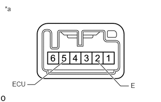
2.75,1.844 2.573,1.844
2.573,1.844 2.083,1.313
true
1.365,1.313 0.74,1.813
0.74,1.813 0.583,1.813
true
0.104,0.104 0.365,0.313
0.26,0.208
10
false
*a
0.26,1.719 0.635,1.917
0.375,0.198
10
false
ECU
2.792,1.75 3.01,1.906
0.219,0.156
10
false
E
| *a | Component without harness connected
(Eco Run Cancel Switch Assembly) |
Measure the resistance according to the value(s) in the table below.
- Standard Resistance:
Tester Connection Switch Condition Specified Condition 5 (ECU) - 2 (E) Pushed Below 1 Ω Not pushed 10 kΩ or higher
If the result is not as specified, replace the eco run cancel switch assembly.
b.

0.531,1.615 0.698,1.615
0.698,1.615 1.104,1.323
true
2.906,1.625 2.719,1.625
2.719,1.625 2.385,1.302
true
0.094,0.115 0.396,0.323
0.302,0.208
10
false
*a
0.219,1.51 0.625,1.698
0.406,0.188
10
false
ILL+
2.948,1.521 3.333,1.719
0.385,0.198
10
false
ILL-
| *a | Component without harness connected
(Eco Run Cancel Switch Assembly) |
Apply battery voltage between the terminals of the switch, and check the illumination condition of the eco run cancel switch assembly.
- OK:
Measurement Condition Specified Condition Battery positive (+) → 6 (ILL+)
Battery negative (-) → 1 (ILL-)Illuminates
If the result is not as specified, replace the eco run cancel switch assembly.