M20D-FKS ENGINE CONTROL SFI SYSTEM P001001 Camshaft Position "A" Actuator Bank 1 General Electrical Failure
DESCRIPTION
The VVT-iE system adjusts the intake valve timing using a motor. Compared to conventional hydraulic VVT systems, the valve timing can be adjusted within a wider range and can be retarded more when starting the engine. As the VVT-iE system can operate at low engine speeds and when the engine is cold, lower emissions, increased engine power and fuel economy and enhanced startability have been achieved.
If the cam timing control motor with EDU assembly is stuck to the advanced side, the valve overlap will be long and affect the internal EGR. This may lead to poor combustion, rough idling or engine stall.
If the cam timing control motor with EDU assembly is stuck near the most retarded angle (Atkinson cycle), depending on the vehicle conditions, sufficient intake air may not be obtained, causing a lack of power.
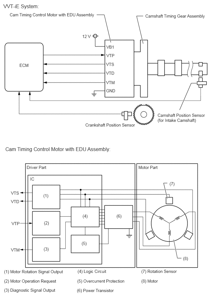
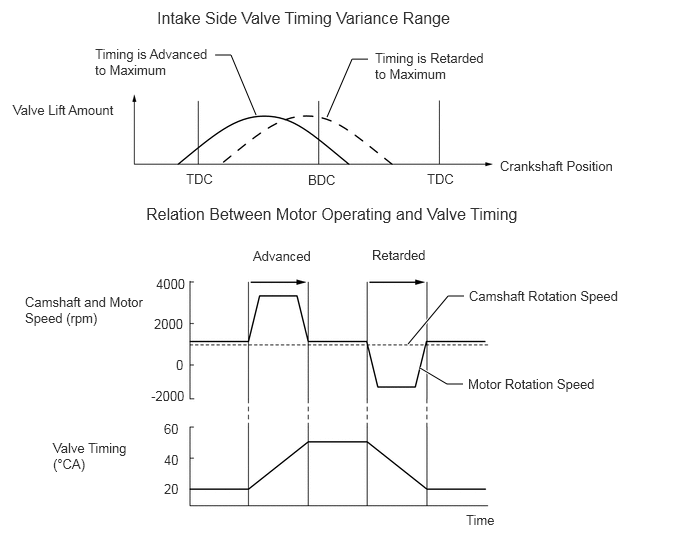
| Part and Terminal Name | Function |
|---|---|
| Cam timing control motor with EDU assembly | Through its electric motor, operates camshaft timing gear assembly. Internal driver detects and performs malfunction diagnosis of motor control, motor speed and rotation direction. |
| Camshaft timing gear assembly | Changes valve timing by rotating camshaft timing gear. |
| ECM | Outputs target speed and motor rotation direction in response to driving conditions. |
| VB1 | Power supply (when ignition switch is ON, battery voltage is 12 V or higher) |
| GND | Power supply ground |
| VTP | Inputs motor activation signal from ECM. |
| VTS | Outputs actual motor speed. |
| VTD | Outputs actual rotation direction. |
| VTM | Outputs malfunction diagnosis results as a duty ratio.
·
Open circuit in VTP and VTM ·
Normal ·
Internal malfunction in driver ·
Malfunction in motor rotation sensor of driver |
| DTC No. | Detection Item | DTC Detection Condition | Trouble Area | MIL | Memory | Note |
|---|---|---|---|---|---|---|
| P001001 | Camshaft Position "A" Actuator Bank 1 General Electrical Failure | One of the following conditions is met for 3 seconds or more (1 trip detection logic).
·
Cam timing control motor IC has overheated. ·
Open in cam timing control motor circuit. ·
Overcurrent is detected in cam timing control motor. |
·
Cam timing control motor with EDU assembly ·
Camshaft timing gear assembly |
Comes on | DTC stored | SAE: P0010 |
| Vehicle Condition | Fail-Safe |
|---|---|
·
Engine difficult to start ·
Lack of power |
The cam timing control motor with EDU assembly is operated to the most retarded position. |
MONITOR DESCRIPTION
This DTC is output when an IC overheat malfunction or an overcurrent malfunction is detected in the cam timing control motor with EDU assembly. The cam timing control motor with EDU assembly is equipped with a self diagnostic function, which is used to output diagnosis signals (VTM) to the ECM. If the ECM receives a motor driver interior malfunction signal, the ECM will illuminate the MIL and store this DTC.
CONFIRMATION DRIVING PATTERN
- HINT:
- ·
After repair has been completed, clear the DTC and then check that the vehicle has returned to normal by performing the following All Readiness check procedure.
·When clearing the permanent DTCs, refer to the "CLEAR PERMANENT DTC" procedure.
Connect the GTS to the DLC3.
Turn the ignition switch to ON.
Turn the GTS on.
Clear the DTCs (even if no DTCs are stored, perform the clear DTC procedure).
Turn the ignition switch off and wait for at least 30 seconds.
Turn the ignition switch to ON.
Turn the GTS on.
Start the engine and warm it up (until the engine coolant temperature 75°C (167°F) or higher) with all the accessories switched off [A].
Idle the engine for 10 seconds or more [B].
Enter the following menus: Powertrain / Engine / Trouble Codes [C].
Read the pending DTCs.
- HINT:
- ·
If a pending DTC is output, the system is malfunctioning.
·If a pending DTC is not output, perform the following procedure.
Enter the following menus: Powertrain / Engine / Utility / All Readiness.
Input the DTC: P001001.
Check the DTC judgment result.
| GTS Display | Description |
|---|---|
| NORMAL | ·
DTC judgment completed ·
System normal |
| ABNORMAL | ·
DTC judgment completed ·
System abnormal |
| INCOMPLETE | ·
DTC judgment not completed ·
Perform driving pattern after confirming DTC enabling conditions |
- HINT:
- ·
If the judgment result is NORMAL, the system is normal.
·If the judgment result is ABNORMAL, the system has a malfunction.
·If the judgment result is INCOMPLETE, perform steps [A] through [C] again.
·[A] to [C]: Normal judgment procedure.
The normal judgment procedure is used to complete DTC judgment and also used when clearing permanent DTCs.
·When clearing the permanent DTCs, do not disconnect the cable from the battery terminal or attempt to clear the DTCs during this procedure, as doing so will clear the universal trip and normal judgment histories.
CAUTION / NOTICE / HINT
- HINT:
-
Read Freeze Frame Data using the GTS. The ECM records vehicle and driving condition information as Freeze Frame Data the moment a DTC is stored. When troubleshooting, Freeze Frame Data can help determine if the vehicle was moving or stationary, if the engine was warmed up or not, if the air fuel ratio was lean or rich, and other data from the time the malfunction occurred.
PROCEDURE
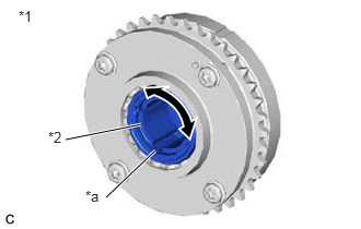
| *1 | Camshaft Timing Gear Assembly |
| *2 | Eccentric Shaft |
| *a | Spline |
Remove the cam timing control motor with EDU assembly.
Check if the eccentric shaft of the camshaft timing gear assembly rotates smoothly.
- NOTICE:
-
If the camshaft is at a position where a valve is about to open, the eccentric shaft may become difficult to rotate.
- OK:
Rotates smoothly.
- HINT:
-
Perform "Inspection After Repair" after replacing the camshaft timing gear assembly, or removing or replacing the cam timing control motor with EDU assembly.
- Result:
Proceed to OK NG
OK
NG