PARKING BRAKE ELECTRIC PARKING BRAKE SYSTEM(for Gasoline Model) C060962 Electric Parking Brake Switch Signal Compare Failure
DESCRIPTION
When the electric parking brake switch (integration control and panel assembly) is pulled, a lock request signal is sent from the skid control ECU (brake actuator assembly) to the parking brake actuator assembly. When the electric parking brake switch (integration control and panel assembly) is pushed, a release request signal is sent from the skid control ECU (brake actuator assembly) to the parking brake actuator assembly.
| DTC No. | Detection Item | DTC Detection Condition | Trouble Area | Memory | Note |
|---|---|---|---|---|---|
| C060962 | Electric Parking Brake Switch Signal Compare Failure | ·
Parking brake switch open or short circuit is detected for 1 second or more ·
Parking brake switch stuck malfunction |
·
Electric parking brake switch (integration control and panel assembly) ·
Wire harness or connector ·
Skid control ECU (brake actuator assembly) |
DTC stored | An electric parking brake system malfunction is displayed on the multi-information display. |
| Vehicle Condition | ||||
|---|---|---|---|---|
| Pattern 1 | Pattern 2 | Pattern 3 | ||
| Diagnosis Condition | - | - | - | - |
| Malfunction Status | Parking brake switch open circuit is detected | ○ | - | - |
| Parking brake switch short circuit is detected | - | ○ | - | |
| Parking brake switch stuck malfunction | - | - | ○ | |
| Detection Time | 1 second or more | 1 second or more | - | |
| Number of Trips | 1 trip | 1 trip | 1 trip | |
WIRING DIAGRAM
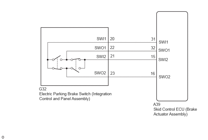
CAUTION / NOTICE / HINT
- NOTICE:
- ·
If the electric parking brake switch (integration control and panel assembly) is held near the lock position but not fully in the lock position for 1 second or more, a DTC may be stored due to one of the two contacts being ON while the other is OFF. (This is not a system malfunction.)
·The electric parking brake may still operate up to 20 seconds after the ignition switch is turned off. Before disconnecting connectors or fuses, turn the ignition switch off and wait 20 seconds or more.
·After replacing the skid control ECU (brake actuator assembly), perform acceleration sensor zero point calibration and store system information memorization.
·When replacing the skid control ECU (brake actuator assembly), operate the electric parking brake switch (integration control and panel assembly) as the parking brake indicator light blinks when the ignition switch is first turned to ON.
PROCEDURE
Remove the electric parking brake switch (integration control and panel assembly).
Inspect the electric parking brake switch (integration control and panel assembly).
- Result:
Proceed to OK NG
OK
NG
Disconnect the G32 electric parking brake switch (integration control and panel assembly) connector.
Disconnect the A39 skid control ECU (brake actuator assembly) connector.
Measure the resistance according to the value(s) in the table below.
- Standard Resistance:
Tester Connection Condition Specified Condition A39-31 (SWI1) - G32-20 (SWI1) Always Below 1 Ω A39-32 (SWO1) - G32-22 (SWO1) Always Below 1 Ω A39-15 (SWI2) - G32-21 (SWI2) Always Below 1 Ω A39-16 (SWO2) - G32-23 (SWO2) Always Below 1 Ω A39-31 (SWI1) or G32-20 (SWI1) - Body ground Always 10 kΩ or higher A39-32 (SWO1) or G32-22 (SWO1) - Body ground Always 10 kΩ or higher A39-15 (SWI2) or G32-21 (SWI2) - Body ground Always 10 kΩ or higher A39-16 (SWO2) or G32-23 (SWO2) - Body ground Always 10 kΩ or higher
- Result:
Proceed to OK NG
OK
NG
Clear the DTCs.
- Chassis > Brake/EPB > Clear DTCs
- 50002 435
Turn the ignition switch off.
- Result:
Proceed to NEXT
NEXT
Check for DTCs.
- Chassis > Brake/EPB > Trouble Codes
- 50001 435
- Result:
Result Proceed to DTCs are output A DTCs are not output B
A
B