SLIDING ROOF / CONVERTIBLE SLIDING ROOF HOUSING(for Moon Roof) REASSEMBLY
PROCEDURE

 63209
1.INSTALL ROOF WIND DEFLECTOR PANEL SUB-ASSEMBLY
63209
1.INSTALL ROOF WIND DEFLECTOR PANEL SUB-ASSEMBLY
Attach the guide as shown in the illustration to install the roof wind deflector panel sub-assembly in the direction indicated by the arrow (1) shown in the illustration.
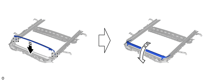

|
Install in this Direction (1) | 
|
Install in this Direction (2) |
Hold down in the direction indicated by the arrow (2) shown in the illustration.
Attach the 2 springs to the 2 guides of the roof wind deflector panel sub-assembly shown in the illustration.
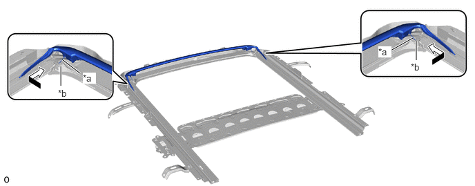
| *a | Spring | *b | Guide |
63205A
2.INSTALL SLIDING ROOF DRIVE CABLE SUB-ASSEMBLY
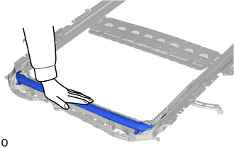
Hold the roof wind deflector panel sub-assembly until the sliding roof drive cable sub-assembly goes over the roof wind deflector panel sub-assembly.
Wearing protective gloves, place your hand at the position shown in the illustration, slide the sliding roof drive cable sub-assembly in the direction indicated by the arrow, and then install the sliding roof drive cable sub-assembly.
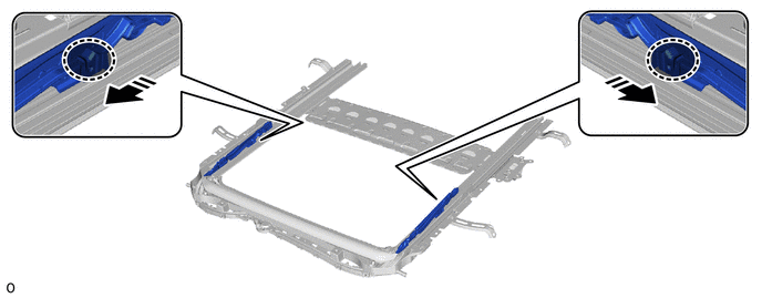

|
Place Hand Here |
|
Slide in this Direction |
Adjust Fully Closed Position:
Place your hand at the position shown in the illustration, slide the sliding roof drive cable LH in either direction and align the alignment marks as shown in the illustration.
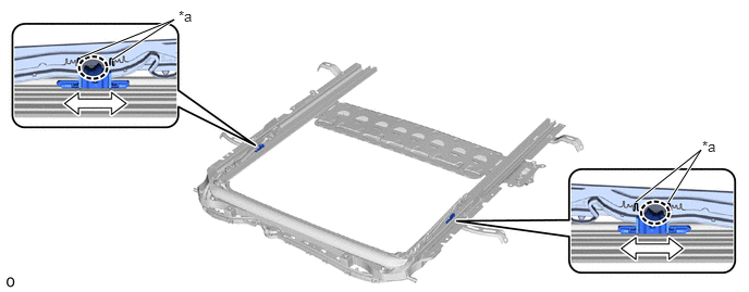
| *a | Alignment Mark | - | - |
|
|
Place Hand Here | - | - |
- CAUTION:
-
Wear protective gloves when performing work.
63214F
3.INSTALL REAR ROOF DRIP CHANNEL
Insert the rear roof drip channel into the sliding roof housing sub-assembly as shown in the illustration.
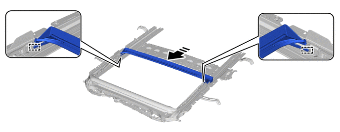
|
|
Install in this Direction | - | - |
Attach the guide as shown in the illustration to install the rear roof drip channel.
63306
4.INSTALL SUNSHADE TRIM SUB-ASSEMBLY
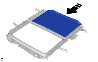
|
|
Install in this Direction |
Insert the sunshade trim sub-assembly into the sliding roof housing sub-assembly as shown in the illustration to install it.
Install the rear No. 1 sliding roof guide stopper.
- HINT:
-
Use the same procedure for the RH and LH sides.
Install the rear No. 1 sliding roof guide stopper in the direction indicated by the arrow (1) shown in the illustration.
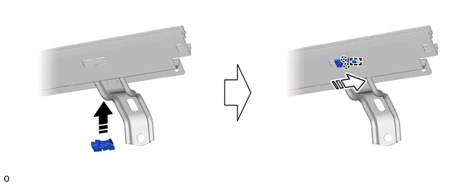
|
|
Install in this Direction (1) |
|
Install in this Direction (2) |
Attach the guide and claw in the direction indicated by the arrow (2) shown in the illustration.
Install the No. 1 sliding roof piece sub-assembly LH and No. 1 sliding roof piece sub-assembly RH.
Attach the guide and install the No. 1 sliding roof piece sub-assembly LH and No. 1 sliding roof piece sub-assembly RH in the direction indicated by the arrow shown in the illustration.
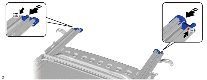
|
|
Install in this Direction | - | - |
Install the 2 screws.
63260H
5.INSTALL SLIDING ROOF DRIVE GEAR ASSEMBLY
Apply MP grease to the gear of the sliding roof drive gear assembly.
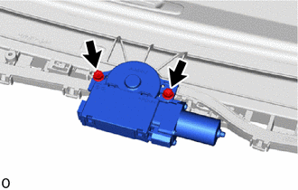
Temporarily install the sliding roof drive gear assembly with the 2 bolts.
Tighten the 2 bolts.
- NOTICE:
-
While balancing the bolt upright, tighten it evenly.
- Torque:
- 5.4 N*m (55 kgf*cm, 48 in.*lbf)
63231C
6.INSTALL ROOM LIGHT BRACKET
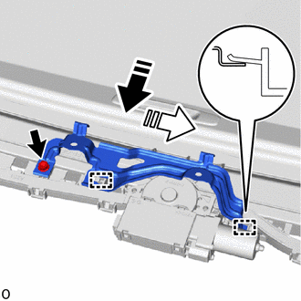
|
|
Install in this Direction (1) |
|
|
Install in this Direction (2) |
Attach the guide in the direction indicated by the arrow (1) shown in the illustration.
Install the room light bracket in the direction indicated by the arrow (2) shown in the illustration.
Install the bolt.
- Torque:
- 5.4 N*m (55 kgf*cm, 48 in.*lbf)