AUDIO / VIDEO RADIO ANTENNA CORD(for Roof) INSTALLATION
PROCEDURE

 86101J
1.INSTALL NO. 2 ANTENNA CORD SUB-ASSEMBLY
86101J
1.INSTALL NO. 2 ANTENNA CORD SUB-ASSEMBLY
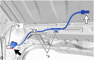
| *a | Clamp |
| *b | Guide |

|
Bolt |

|
Connector |
Attach the clamp.
Connect the connector.
Attach the guide to install the No. 2 antenna cord sub-assembly with the bolt.
- Torque:
- 10 N*m (102 kgf*cm, 7 ft.*lbf)
86101D
2.INSTALL NO. 3 ANTENNA CORD SUB-ASSEMBLY
When double-sided tape cannot be reused:
Remove the old double-sided tape.
Remove the peeling paper on one side trying not to touch the adhesional surface, and attach new double-sided tape to the position indicated in the illustration.
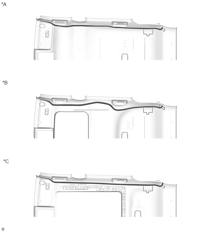
| *A | for Normal Roof | *B | for Moon Roof |
| *C | for Panoramic Moon Roof | - | - |

|
Double-sided Tape | - | - |
- NOTICE:
-
Attach securely so that the double-sided tape will not shift or peel off.
Remove the peeling paper of the double-sided tape trying not to touch the adhesional surface.
for Normal Roof:
Install the No. 3 antenna cord sub-assembly with the tape aligned to each marking of the roof headlining assembly as shown in the illustration.

| *1 | No. 3 Antenna Cord Sub-assembly | - | - |
| *a | Marking | *b | Adjustment Area |

|
Tape | 
|
Marking Tape |
- HINT:
- ·
Secure the surplus of the No. 3 antenna cord sub-assembly at the adjustment area of the illustration.
·Secure the front part of the No. 3 antenna cord sub-assembly aligning the edge of the positioning tape and tab section of the roof headlining assembly.
·Secure the rear part of the No. 3 antenna cord sub-assembly aligning the edge of the positioning tape and tab section of the roof headlining assembly.
for Moon Roof:
Install the No. 3 antenna cord sub-assembly with the tape aligned to each marking of the roof headlining assembly as shown in the illustration.
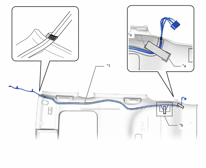
| *1 | No. 3 Antenna Cord Sub-assembly | - | - |
| *a | Marking | *b | Adjustment Area |
|
|
Tape |
|
Marking Tape |
- HINT:
- ·
Secure the surplus of the No. 3 antenna cord sub-assembly at the adjustment area of the illustration.
·Secure the front part of the No. 3 antenna cord sub-assembly aligning the edge of the positioning tape and tab section of the roof headlining assembly.
·Secure the rear part of the No. 3 antenna cord sub-assembly aligning the edge of the positioning tape and tab section of the roof headlining assembly.
for Panoramic Moon Roof:
Install the No. 3 antenna cord sub-assembly with the tape aligned to each marking of the roof headlining assembly as shown in the illustration.

| *1 | No. 3 Antenna Cord Sub-assembly | - | - |
| *a | Marking | *b | Adjustment Area |
|
|
Tape |
|
Marking Tape |
- HINT:
- ·
Secure the surplus of the No. 3 antenna cord sub-assembly at the adjustment area of the illustration.
·Secure the front part of the No. 3 antenna cord sub-assembly aligning the edge of the positioning tape and tab section of the roof headlining assembly.
·Secure the rear part of the No. 3 antenna cord sub-assembly aligning the edge of the positioning tape and tab section of the roof headlining assembly.
3.INSTALL ROOF HEADLINING ASSEMBLY
4.INSPECT SEAT HEATER SYSTEM (w/ Seat Heater System)