☰ Toyota Levin Turbo☰ فهرستVehicle Interior › THEFT DETERRENT / KEYLESS ENTRY › IMMOBILISER SYSTEM(w/o Smart Entry and Start System)
RM3660EC
_58
Vehicle Interior
_080747
THEFT DETERRENT / KEYLESS ENTRY
_0392034
IMMOBILISER SYSTEM(w/o Smart Entry and Start System)
U
THEFT DETERRENT / KEYLESS ENTRY IMMOBILISER SYSTEM(w/o Smart Entry and Start System) TERMINALS OF ECU
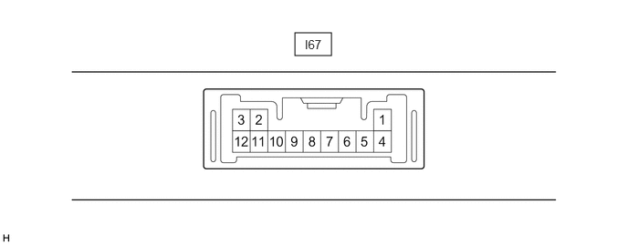
CHECK TRANSPONDER KEY ECU ASSEMBLY
3.365,0.375 3.781,0.635
0.417,0.26
3.479,0.427 3.938,0.625
0.458,0.198
10
false
I67
a.
Disconnect the I67 transponder key ECU assembly connector.
b.
Measure the resistance and voltage according to the value(s) in the table below.
- HINT:
-
Measure the values on the wire harness side with the connector disconnected.
| Terminal No. (Symbol) | Terminal Description | Condition | Specified Condition | Related Data List Item / DTC |
|---|---|---|---|---|
| I67-4 (+B) - I67-12 (GND) | Battery | Always | 11 to 14 V | +B |
| I67-5 (KSW) - I67-12 (GND) | Unlock warning switch signal | No door control transmitter assembly in ignition key cylinder | 10 kΩ or higher | ·
B2780 ·
Key SW |
| Door control transmitter assembly in ignition key cylinder | Below 1 Ω | |||
| I67-12 (GND) - Body ground | Ground | Always | Below 1 Ω | - |
c.
Reconnect the I67 transponder key ECU assembly connector.
d.
Measure the voltage and check for pulses according to the value(s) in the table below.
| Terminal No. (Symbol) | Terminal Description | Condition | Specified Condition | Related Data List Item / DTC |
|---|---|---|---|---|
| I67-6 (IG) - I67-12 (GND) | Ignition switch signal | Ignition switch off | Below 1 V | IG SW |
| Ignition switch ON | 11 to 14 V | |||
| I67-8 (IND) - I67-12 (GND) | Security indicator light signal | No door control transmitter assembly in ignition key cylinder, or 20 sec. elapsed after turning ignition switch to ACC or off (immobiliser system set) | Pulse generation | Immobiliser |
| Door control transmitter assembly in ignition key cylinder (immobiliser system unset) | Below 1 V | |||
| I67-9 (D) - I67-12 (GND) | DLC3 communication | Without communication | Below 1 V | - |
| During communication | Pulse generation | |||
| I67-2 (ANT1) - I67-12 (GND) | Transponder key amplifier power source | No door control transmitter assembly in ignition key cylinder | Below 1 V | - |
| Within 3 seconds of inserting door control transmitter assembly into ignition key cylinder | Pulse generation
(See waveform 1) |
|||
| I67-3 (ANT2) - I67-12 (GND) | Transponder key amplifier communication signal | No door control transmitter assembly in ignition key cylinder | Below 1 V | - |
| Within 3 seconds of inserting door control transmitter assembly into ignition key cylinder | Pulse generation
(See waveform 2) |
|||
| I67-10 (EFII) - I67-12 (GND) | ECM input signal | Ignition switch off | 11 to 14 V | - |
| Within 3 seconds of starter operation and initial combustion, or within 3 seconds of ignition switch first being turned to ON after cable disconnected and reconnected to negative (-) battery terminal | Pulse generation
(See waveform 3) |
|||
| I67-11 (EFIO) - I67-12 (GND) | ECM output signal | Ignition switch off | Below 1 V | - |
| Within 3 seconds of starter operation and initial combustion, or within 3 seconds of ignition switch first being turned to ON after cable disconnected and reconnected to negative (-) battery terminal | Pulse generation
(See waveform 4) |
e.
Using an oscilloscope, check the waveform.
i.
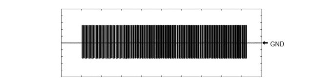
Waveform 1 (Reference)
5.76,0.854 6.219,1.052
0.458,0.198
10
GND
| Tester Connection | I67-2 (ANT1) - I67-12 (GND) |
| Tool Setting | 20 V/DIV., 2 s./DIV. |
| Condition | Within 3 seconds of inserting door control transmitter assembly into ignition key cylinder |
ii.
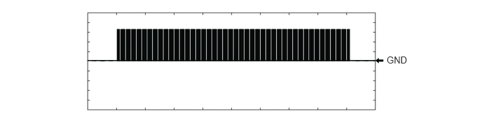
Waveform 2 (Reference)
5.75,0.813 6.208,1.01
0.458,0.198
10
false
GND
| Tester Connection | I67-3 (ANT2) - I67-12 (GND) |
| Tool Setting | 20 V/DIV., 2 s./DIV. |
| Condition | Within 3 seconds of inserting door control transmitter assembly into ignition key cylinder |
iii.
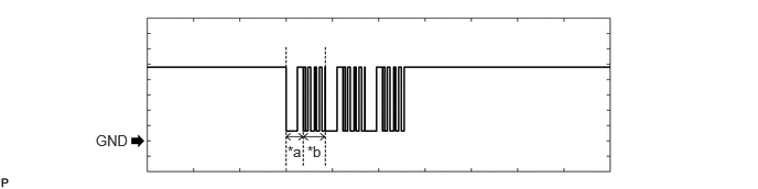
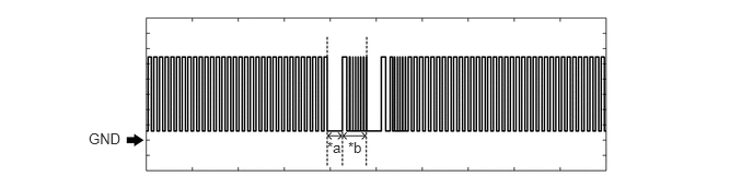
Waveform 3 (Reference)
0.906,1.25 1.365,1.448
0.458,0.198
10
GND
2.719,1.354 3.177,1.552
0.458,0.198
10
*a
2.906,1.354 3.365,1.552
0.458,0.198
10
*b
| *a | Approximately 160 ms. | *b | Approximately 270 ms. |
| Tester Connection | I67-10 (EFII) - I67-12 (GND) |
| Tool Setting | 2 V/DIV., 500 ms./DIV. |
| Condition | Within 3 seconds of starter operation and initial combustion, or within 3 seconds of ignition switch first being turned to ON after cable disconnected and reconnected to negative (-) battery terminal |
iv.
Waveform 4 (Reference)
0.844,1.24 1.302,1.438
0.458,0.198
10
GND
3.115,1.323 3.344,1.531
0.229,0.208
10
*a
3.313,1.323 3.542,1.531
0.229,0.208
10
*b
| *a | Approximately 160 ms. | *b | Approximately 270 ms. |
| Tester Connection | I67-11 (EFIO) - I67-12 (GND) |
| Tool Setting | 2 V/DIV., 500 ms./DIV. |
| Condition | Within 3 seconds of starter operation and initial combustion, or within 3 seconds of ignition switch first being turned to ON after cable disconnected and reconnected to negative (-) battery terminal |
CHECK ECM
2.156,0.354 2.604,0.604
0.448,0.25
5.104,0.365 5.552,0.615
0.448,0.25
2.229,0.396 2.688,0.594
0.458,0.198
10
false
C156
5.167,0.406 5.625,0.604
0.458,0.198
10
false
A142
a.
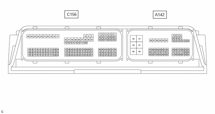
Measure the voltage and check for pulses according to the value(s) in the table below.
| Terminal No. (Symbol) | Terminal Description | Condition | Specified Condition | Related Data List Item / DTC |
|---|---|---|---|---|
| A142-55 (IMO) - A142-22 (E1) | Transponder key ECU assembly communication output | Ignition switch off | 11 to 14 V | - |
| Within 3 seconds of starter operation and initial combustion, or within 3 seconds of ignition switch first being turned to ON after cable disconnected and reconnected to negative (-) battery terminal | Pulse generation
(See waveform 1) |
- | ||
| A142-54 (IMI) - A142-22 (E1) | Transponder key ECU assembly communication input | Ignition switch off | Below 1 V | - |
| Within 3 seconds of starter operation and initial combustion, or within 3 seconds of ignition switch first being turned to ON after cable disconnected and reconnected to negative (-) battery terminal | Pulse generation
(See waveform 2) |
- |
b.
Using an oscilloscope, check the waveform.
i.
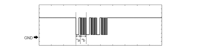
Waveform 1 (Reference)
0.865,1.271 1.323,1.469
0.458,0.198
10
GND
2.719,1.354 2.885,1.521
0.167,0.167
10
*a
2.906,1.354 3.073,1.521
0.167,0.167
10
*b
| *a | Approximately 160 ms. | *b | Approximately 270 ms. |
| Tester Connection | A142-55 (IMO) - A142-22 (E1) |
| Tool Setting | 2 V/DIV., 500 ms./DIV. |
| Condition | Within 3 seconds of starter operation and initial combustion, or within 3 seconds of ignition switch first being turned to ON after cable disconnected and reconnected to negative (-) battery terminal |
ii.
Waveform 2 (Reference)
0.844,1.24 1.302,1.438
0.458,0.198
10
GND
3.115,1.323 3.344,1.531
0.229,0.208
10
*a
3.313,1.323 3.542,1.531
0.229,0.208
10
*b
| *a | Approximately 160 ms. | *b | Approximately 270 ms. |
| Tester Connection | A142-54 (IMI) - A142-22 (E1) |
| Tool Setting | 2 V/DIV., 500 ms./DIV. |
| Condition | Within 3 seconds of starter operation and initial combustion, or within 3 seconds of ignition switch first being turned to ON after cable disconnected and reconnected to negative (-) battery terminal |