AUDIO / VIDEO INSTRUMENT PANEL SPEAKER INSPECTION
PROCEDURE

 1.INSPECT FRONT NO. 2 SPEAKER ASSEMBLY
except 10.25 Inch Display:
With the speaker installed, check that there is no looseness or other abnormalities.
Check that there is no foreign matter in the speaker, no tears on the speaker cone or other abnormalities.
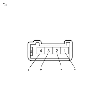
| *a | Component without harness connected
(Front No. 2 Speaker Assembly) |
Measure the resistance of the speaker.
- Standard Resistance:
Tester Connection Condition Specified Condition 4 (+) - 2 (-) Always 10 kΩ or higher 1 (-) - 2 (-) Always Below 1 Ω 3 (+) - 4 (+) Always Below 1 Ω
If the result is not as specified, replace the speaker.
When there is a possibility that either the right or left speaker is malfunctioning, interchange the speakers and perform an inspection. If the malfunction disappears after interchanging the speakers, replace the malfunctioning speaker.
- HINT:
-
Connect all connectors to the speakers when performing an inspection. If the result is not as specified, replace the speaker.
for 10.25 Inch Display:
With the speaker installed, check that there is no looseness or other abnormalities.
Check that there is no foreign matter in the speaker, no tears on the speaker cone or other abnormalities.
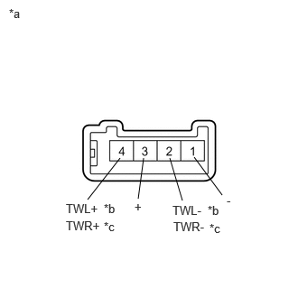
| *a | Component without harness connected
(Front No. 2 Speaker Assembly) |
| *b | for LH Side |
| *c | for RH Side |
Measure the resistance of the speaker.
- Standard Resistance:
for LH Side: Tester Connection Condition Specified Condition 4 (TWL+) - 2 (TWL-) Always 10 kΩ or higher 1 (-) - 2 (TWL-) Always Below 1 Ω 3 (+) - 4 (TWL+) Always Below 1 Ω
for RH Side: Tester Connection Condition Specified Condition 4 (TWR+) - 2 (TWR-) Always 10 kΩ or higher 1 (-) - 2 (TWR-) Always Below 1 Ω 3 (+) - 4 (TWR+) Always Below 1 Ω
If the result is not as specified, replace the speaker.
When there is a possibility that either the right or left speaker is malfunctioning, interchange the speakers and perform an inspection. If the malfunction disappears after interchanging the speakers, replace the malfunctioning speaker.
- HINT:
-
Connect all connectors to the speakers when performing an inspection. If the result is not as specified, replace the speaker.