BRAKE (REAR) REAR BRAKE(w/ Electric Parking Brake) INSTALLATION
CAUTION / NOTICE / HINT
- NOTICE:
- ·
Immediately after installing the brake pads, the braking performance may be reduced. Always perform a road test in a safe place while paying attention to the surroundings.
·After replacing the rear disc brake pads, the brake pedal may feel soft due to clearance between the rear disc brake pads and rear disc. Depress the brake pedal several times until the brake pedal feels firm.
·After replacing the rear disc brake pads, always perform a road test to check the braking performance and check for vibrations.
- HINT:
- ·
Use the same procedure for the RH side and LH side.
·The following procedure is for the LH side.
PROCEDURE

 42431
1.INSTALL REAR DISC
42431
1.INSTALL REAR DISC
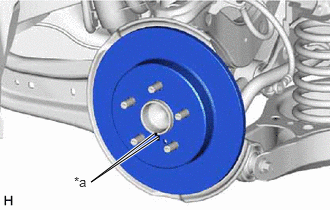
| *a | Matchmark |
Align the matchmarks of the rear disc and rear axle hub and bearing assembly, and install the rear disc.
- NOTICE:
-
When replacing the rear disc with a new one, select the installation position where the rear disc has minimal runout.
47822
2.INSTALL REAR DISC BRAKE CYLINDER MOUNTING
Install the rear disc brake cylinder mounting to the rear axle carrier sub-assembly with the 2 bolts.
- Torque:
- 107 N*m (1091 kgf*cm, 79 ft.*lbf)
3.INSTALL REAR DISC BRAKE BUSHING DUST BOOT
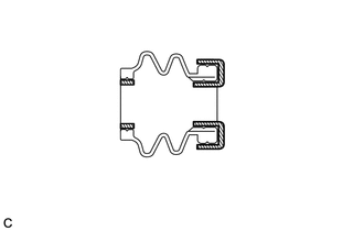

|
Lithium Soap Base Glycol Grease |
Apply a light layer of lithium soap base glycol grease to the entire circumference of 2 new rear disc brake bushing dust boots.
- HINT:
-
Apply more than 0.3 g (0.01 oz) of lithium soap base glycol grease to each rear disc brake bushing dust boot.
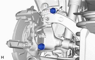
Install the 2 rear disc brake bushing dust boots to the rear disc brake cylinder mounting.
4.INSTALL REAR DISC BRAKE CYLINDER SLIDE PIN
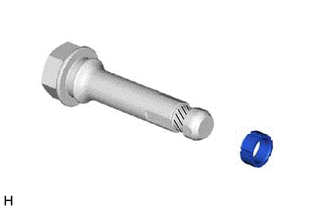
|
|
Lithium Soap Base Glycol Grease |
Apply a light layer of lithium soap base glycol grease to the contact surface of the rear No. 2 disc brake cylinder slide pin.
Install a new rear disc brake cylinder slide bushing to the rear No. 2 disc brake cylinder slide pin.
|
|
Lithium Soap Base Glycol Grease |
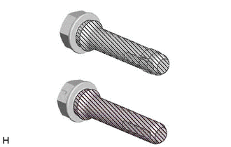
Apply a light layer of lithium soap base glycol grease to the sliding part and the sealing surfaces of the rear No. 1 disc brake cylinder slide pin and rear No. 2 disc brake cylinder slide pin.
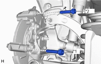
| *1 | Rear No. 1 Disc Brake Cylinder Slide Pin |
| *2 | Rear No. 2 Disc Brake Cylinder Slide Pin |
Install the rear No. 1 disc brake cylinder slide pin and rear No. 2 disc brake cylinder slide pin to the rear disc brake cylinder mounting.
Push the rear No. 1 disc brake cylinder slide pin and rear No. 2 disc brake cylinder slide pin into each rear disc brake bushing dust boot to engage the pins to the boots.
5.INSTALL REAR DISC BRAKE PAD SUPPORT PLATE
Install the 4 rear disc brake pad support plates to the rear disc brake cylinder mounting.
- NOTICE:
-
Be sure to install each rear disc brake pad support plate in the correct position and direction.
04946
6.INSTALL REAR DISC BRAKE ANTI-SQUEAL SHIM KIT
04466
7.INSTALL REAR DISC BRAKE PAD
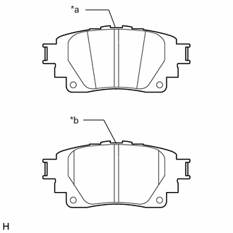
| *a | Inner Side |
| *b | Outer Side |
Install the 2 rear disc brake pads to the rear disc brake cylinder mounting.
- NOTICE:
-
Install the rear disc brake pad so that the rear disc brake pad wear indicator plate is mounted on the lower side of the vehicle.
47850
8.INSTALL REAR DISC BRAKE CYLINDER ASSEMBLY
Hold the 2 rear disc brake cylinder slide pins, and install the rear disc brake cylinder assembly to the rear disc brake cylinder mounting with 2 bolts.
- Torque:
- 34.3 N*m (350 kgf*cm, 25 ft.*lbf)
- NOTICE:
-
If bleeding of air from the rear disc brake cylinder assembly will be performed, reuse the bolts. If bleeding of air from the rear brake cylinder assembly will not be performed, install new bolts.
46310B
9.INSTALL PARKING BRAKE ACTUATOR ASSEMBLY
890C0A
10.CONNECT NO. 2 PARKING BRAKE WIRE ASSEMBLY
47319F
11.CONNECT REAR FLEXIBLE HOSE
Connect the rear flexible hose to the rear disc brake cylinder assembly with a new union bolt and a new gasket.
- Torque:
- 29 N*m (296 kgf*cm, 21 ft.*lbf)
- NOTICE:
-
Install the rear flexible hose lock securely into the lock hole in the rear disc brake cylinder assembly.
12. BLEED BRAKE LINE
47850
13.BLEED REAR DISC BRAKE CYLINDER ASSEMBLY
- CAUTION:
-
If the rear disc brake cylinder assembly has been disassembled, perform air bleeding for the rear disc brake cylinder assembly.
- HINT:
- ·
Use the same procedure for the RH side and LH side.
·The following procedure is for the LH side.
·While performing air bleeding of the rear disc brake cylinder assembly, the bolts can be reused during the bleeding procedure. After air bleeding is complete, replace the bolts with new ones.
Perform the procedure to enter rear disc brake pad replacement mode 5 times.
Release the parking brake.
Disconnect the No. 2 parking brake wire assembly connector from the parking brake actuator assembly.
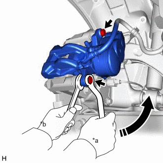
| *a | Turn |
| *b | Hold |
Hold the 2 rear disc brake cylinder slide pins and remove the 2 bolts and separate the rear disc brake cylinder assembly from the rear disc brake cylinder mounting.(*1)
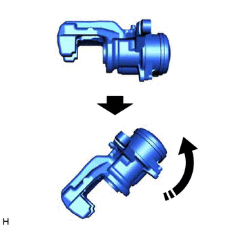
Hold the rear disc brake cylinder assembly horizontally, then tilt it 45° toward the rear disc brake bleeder plug side as shown in the illustration.(*2)
Temporarily install the rear disc brake cylinder assembly to the rear disc brake cylinder mounting with the 2 bolts.(*3)
Remove the center cowl top ventilator louver.
Remove the brake master cylinder reservoir filler cap assembly.
Add brake fluid to keep the level between the MIN and MAX lines of the reservoir while bleeding the brakes.
- NOTICE:
- ·
Make sure that there is sufficient brake fluid in the reservoir.
·Do not remove the filter from the brake master cylinder reservoir assembly and be sure to fill the brake master cylinder reservoir assembly with new brake fluid to avoid any potential contamination of the brake system. Contamination, for example by dirt particles or mineral oil, could lead to functional brake problems.
·If brake fluid leaks onto any painted surface, immediately wash it off.
Remove the rear disc brake bleeder plug cap.
Connect a vinyl tube to the rear disc brake bleeder plug.
Depress the brake pedal several times, and then loosen the rear disc brake bleeder plug with the pedal depressed.(*4)
When fluid stops coming out, tighten the rear disc brake bleeder plug and release the brake pedal.(*5)
- NOTICE:
-
Repeat steps (*4) through (*5) until there are no signs of air in the brake fluid.
Repeat steps (*1) through (*5) 3 times.
- NOTICE:
-
If there is still air in the system after performing steps (*1) through (*5) 3 times, repeat the steps (*1) through (*5) until the air has been bled.
Tighten the rear disc brake bleeder plug completely.
- Torque:
- 8.3 N*m (85 kgf*cm, 73 in.*lbf)
Install the rear disc brake bleeder plug cap.
Hold the 2 rear disc brake cylinder slide pins, and install the rear disc brake cylinder assembly to the rear disc brake cylinder mounting with 2 new bolts.
- Torque:
- 34.3 N*m (350 kgf*cm, 25 ft.*lbf)
Connect the No. 2 parking brake wire assembly connector to the parking brake actuator assembly.
Inspect for brake fluid leaks.
Inspect the brake fluid level in the reservoir.
Install the brake master cylinder reservoir filler cap assembly.
Install the center cowl top ventilator louver.
14.INSTALL REAR WHEEL
15.CONNECT CABLE TO NEGATIVE AUXILIARY BATTERY TERMINAL (for HV Model)
for 8ZR-FXE: Click hereGeneral>MAINTENANCE>8ZR-FXE AUXILIARY BATTERY>INSTALLATION202304,999999,_V1,_080956,_0392376,RM100000002ACL8,
for M20F-FXS, M20G-FXS: Click hereGeneral>MAINTENANCE>M20F-FXS, M20G-FXS AUXILIARY BATTERY>INSTALLATION202307,999999,_V1,_080956,_0611807,RM100000002CK9L,
16. NORMAL CONDITION RECOVERY
for HV Model: Click hereBrake>PARKING BRAKE>ELECTRIC PARKING BRAKE SYSTEM (for HV Model)>TEST MODE PROCEDURE202304,999999,_54,_080740,_0394663,RM100000002B637,
for Gasoline Model: Click hereBrake>PARKING BRAKE>ELECTRIC PARKING BRAKE SYSTEM (for Gasoline Model)>TEST MODE PROCEDURE201906,999999,_54,_080740,_0394664,RM100000001I7FZ,
17. INITIALIZATION AFTER RECONNECTING AUXILIARY BATTERY TERMINAL (for HV Model)
- HINT:
-
When disconnecting and reconnecting the auxiliary battery, there is an automatic learning function that completes learning when the respective system is used.