MIRROR (EXT) OUTER MIRROR SWITCH INSPECTION
PROCEDURE

 84870A
1.INSPECT OUTER MIRROR SWITCH ASSEMBLY (w/o Power Retract Mirror)
84870A
1.INSPECT OUTER MIRROR SWITCH ASSEMBLY (w/o Power Retract Mirror)
Check the mirror select switch and mirror surface adjust switch.

| *a | Mirror Select and Surface Adjust Switch |
| *b | Component without harness connected
(Outer Mirror Switch Assembly) |
Turn the mirror select switch to the L position.
Measure the resistance according to the value(s) in the table below.
- Standard Resistance (for left side):
Tester Connection Condition Specified Condition 2 (VL) - 6 (B)
11 (M+) - 7 (E)Up Below 2 Ω Off 10 kΩ or higher 2 (VL) - 7 (E)
11 (M+) - 6 (B)Down Below 2 Ω Off 10 kΩ or higher 4 (HL) - 6 (B)
11 (M+) - 7 (E)Left Below 2 Ω Off 10 kΩ or higher 4 (HL) - 7 (E)
11 (M+) - 6 (B)Right Below 2 Ω Off 10 kΩ or higher
Turn the mirror select switch to the R position.
Measure the resistance according to the value(s) in the table below.
- Standard Resistance (for right side):
Tester Connection Condition Specified Condition 5 (VR) - 6 (B)
11 (M+) - 7 (E)Up Below 2 Ω Off 10 kΩ or higher 5 (VR) - 7 (E)
11 (M+) - 6 (B)Down Below 2 Ω Off 10 kΩ or higher 3 (HR) - 6 (B)
11 (M+) - 7 (E)Left Below 2 Ω Off 10 kΩ or higher 3 (HR) - 7 (E)
11 (M+) - 6 (B)Right Below 2 Ω Off 10 kΩ or higher
If the result is not as specified, replace the outer mirror switch assembly.
Check that the LED illuminates.
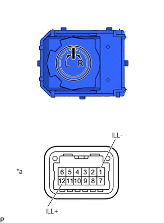
| *a | Component without harness connected
(Outer Mirror Switch Assembly) |
Apply auxiliary battery voltage to the outer mirror switch assembly and check that the LED illuminates.
- OK:
Auxiliary Battery Connection Specified Condition Auxiliary battery positive (+) - 12 (ILL+)
Auxiliary battery negative (-) - 1 (ILL-)LED illuminates
If the result is not as specified, replace the outer mirror switch assembly.
84870A
2.INSPECT OUTER MIRROR SWITCH ASSEMBLY (w/ Power Retract Mirror)
Check the mirror select switch and mirror surface adjust switch.
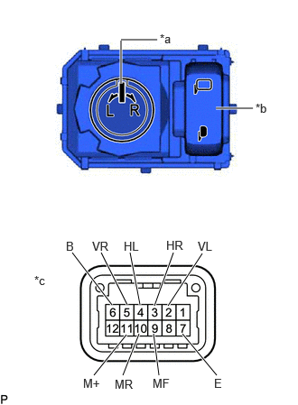
| *a | Mirror Select and Surface Adjust Switch |
| *b | Retractable Outer Mirror Switch |
| *c | Component without harness connected
(Outer Mirror Switch Assembly) |
Turn the mirror select switch to the L position.
Measure the resistance according to the value(s) in the table below.
- Standard Resistance (for left side):
Tester Connection Condition Specified Condition 2 (VL) - 6 (B)
11 (M+) - 7 (E)Up Below 2 Ω Off 10 kΩ or higher 2 (VL) - 7 (E)
11 (M+) - 6 (B)Down Below 2 Ω Off 10 kΩ or higher 4 (HL) - 6 (B)
11 (M+) - 7 (E)Left Below 2 Ω Off 10 kΩ or higher 4 (HL) - 7 (E)
11 (M+) - 6 (B)Right Below 2 Ω Off 10 kΩ or higher
Turn the mirror select switch to the R position.
Measure the resistance according to the value(s) in the table below.
- Standard Resistance (for right side):
Tester Connection Condition Specified Condition 5 (VR) - 6 (B)
11 (M+) - 7 (E)Up Below 2 Ω Off 10 kΩ or higher 5 (VR) - 7 (E)
11 (M+) - 6 (B)Down Below 2 Ω Off 10 kΩ or higher 3 (HR) - 6 (B)
11 (M+) - 7 (E)Left Below 2 Ω Off 10 kΩ or higher 3 (HR) - 7 (E)
11 (M+) - 6 (B)Right Below 2 Ω Off 10 kΩ or higher
If the result is not as specified, replace the outer mirror switch assembly.
Check the retractable outer mirror switch.
Measure the resistance according to the value(s) in the table below.
- Standard Resistance:
Tester Connection Condition Specified Condition 9 (MF) - 6 (B)
10 (MR) - 7 (E)Driving position Below 2 Ω Except Driving position 10 kΩ or higher 10 (MR) - 6 (B)
9 (MF) - 7 (E)Retract position Below 2 Ω Except Retract position 10 kΩ or higher
If the result is not as specified, replace the outer mirror switch assembly.
Check that the LED illuminates.
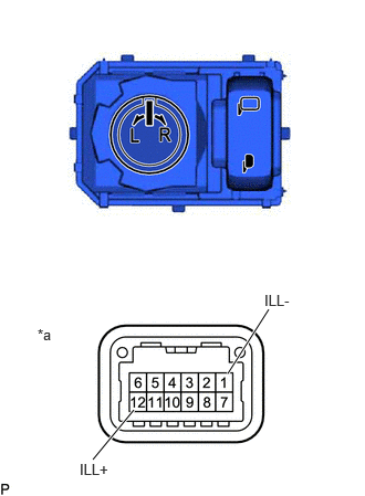
| *a | Component without harness connected
(Outer Mirror Switch Assembly) |
Apply auxiliary battery voltage to the outer mirror switch assembly and check that the LED illuminates.
- OK:
Auxiliary Battery Connection Specified Condition Auxiliary battery positive (+) - 12 (ILL+)
Auxiliary battery negative (-) - 1 (ILL-)LED illuminates
If the result is not as specified, replace the outer mirror switch assembly.
84870A
3.INSPECT OUTER MIRROR SWITCH ASSEMBLY (w/ Automatic Retractable Mirror)
Check the mirror select switch and mirror surface adjust switch.
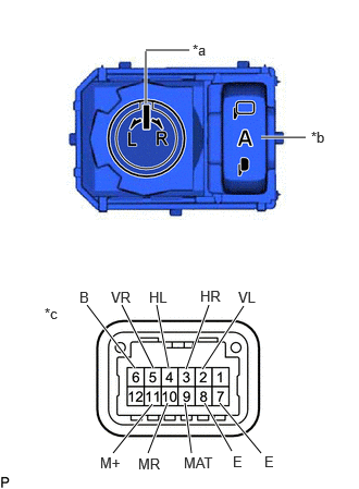
| *a | Mirror Select and Surface Adjust Switch |
| *b | Retractable Outer Mirror Switch |
| *c | Component without harness connected
(Outer Mirror Switch Assembly) |
Turn the mirror select switch to the L position.
Measure the resistance according to the value(s) in the table below.
- Standard Resistance (for left side):
Tester Connection Condition Specified Condition 2 (VL) - 6 (B)
11 (M+) - 7 (E)Up Below 2 Ω Off 10 kΩ or higher 2 (VL) - 7 (E)
11 (M+) - 6 (B)Down Below 2 Ω Off 10 kΩ or higher 4 (HL) - 6 (B)
11 (M+) - 7 (E)Left Below 2 Ω Off 10 kΩ or higher 4 (HL) - 7 (E)
11 (M+) - 6 (B)Right Below 2 Ω Off 10 kΩ or higher
Turn the mirror select switch to the R position.
Measure the resistance according to the value(s) in the table below.
- Standard Resistance (for right side):
Tester Connection Condition Specified Condition 5 (VR) - 6 (B)
11 (M+) - 7 (E)Up Below 2 Ω Off 10 kΩ or higher 5 (VR) - 7 (E)
11 (M+) - 6 (B)Down Below 2 Ω Off 10 kΩ or higher 3 (HR) - 6 (B)
11 (M+) - 7 (E)Left Below 2 Ω Off 10 kΩ or higher 3 (HR) - 7 (E)
11 (M+) - 6 (B)Right Below 2 Ω Off 10 kΩ or higher
If the result is not as specified, replace the outer mirror switch assembly.
Check the retractable outer mirror switch.
Measure the resistance according to the value(s) in the table below.
- Standard Resistance:
Tester Connection Condition Specified Condition 9 (MAT) - 8 (E) AUTO position Below 2 Ω Except AUTO position 10 kΩ or higher 10 (MR) - 8 (E) Retract position Below 2 Ω Except Retract position 10 kΩ or higher
If the result is not as specified, replace the outer mirror switch assembly.
Check that the LED illuminates.
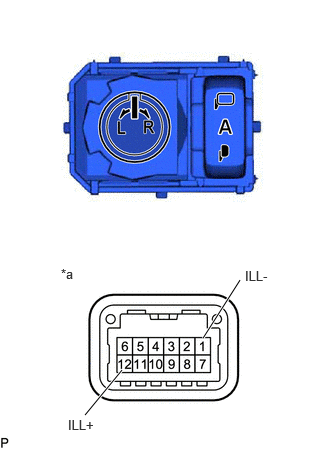
| *a | Component without harness connected
(Outer Mirror Switch Assembly) |
Apply auxiliary battery voltage to the outer mirror switch assembly and check that the LED illuminates.
- OK:
Auxiliary Battery Connection Specified Condition Auxiliary battery positive (+) - 12 (ILL+)
Auxiliary battery negative (-) - 1 (ILL-)LED illuminates
If the result is not as specified, replace the outer mirror switch assembly.