NR Series ENGINE CONTROL SFI SYSTEM TERMINALS OF ECM
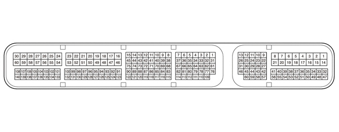
- HINT:
-
The standard voltage, resistance and waveform between each pair of the ECM terminals is shown in the table below. The appropriate conditions for checking each pair of the terminals is also indicated. The result of checks should be compared with the standard voltage, resistance and waveform for each pair of the terminals as displayed in the Specified Condition column. The illustration above can be used as a reference to identify the ECM terminal locations.
| Terminal No. (Symbol) | Wiring Color | Terminal Description | Condition | Specified Condition |
|---|---|---|---|---|
| A46-1 (BATT) - C78-53 (E1) | R - W-B | Battery (for measuring battery voltage and for ECM memory) | Always | 11 to 14 V |
| A46-2 (+B) - C78-53 (E1) | B - W-B | Power source of ECM | Ignition switch ON | 11 to 14 V |
| A46-3 (+B2) - C78-53 (E1) | B - W-B | Power source of ECM | Ignition switch ON | 11 to 14 V |
| A46-6 (IGSW) - C78-53 (E1) | BE - W-B | Ignition switch signal | Ignition switch ON | 11 to 14 V |
| A46-7 (VPMP) - C78-53 (E1) | B - W-B | Vent valve (built into canister pump module) | Ignition switch ON | 11 to 14 V |
| A46-8 (IREL) - C78-53 (E1) | L - W-B | IGN/INJ/D INJ relay operation signal | Engine stopped, ignition switch ON | 0 to 1.5 V |
| A46-9 (STP) - C78-53 (E1) | L - W-B | Stop light switch assembly signal | Brake pedal depressed | 7.5 to 14 V |
| Brake pedal released | 0 to 1.5 V | |||
| A46-10 (ST1-) - C78-53 (E1) | Y - W-B | Stop light switch assembly signal
(opposite to STP terminal) |
Ignition switch ON, brake pedal depressed | 0 to 1.5 V |
| Ignition switch ON, brake pedal released | 7.5 to 14 V | |||
| A46-11 (IWPI) - C78-53 (E1) | V - W-B | Electric water pump assembly signal | Electric water pump assembly operating | Pulse generation |
| A46-13 (CANH) - C78-53 (E1) | GR - W-B | CAN communication signal | Engine stopped, ignition switch ON | Pulse generation
(See waveform 1) |
| A46-14 (EC) - Body ground | W-B - - | Ground | Always | Below 1 Ω |
| A46-20 (MPMP) - C78-53 (E1) | LG - W-B | Leak detection pump (built into canister pump module) | Leak detection pump off | Below 3 V |
| Leak detection pump on | 11 to 14 V | |||
| A46-21 (FPC) - C78-53 (E1) | R - W-B | Fuel pump control | Engine stopped, ignition switch ON | Below 1.5 V |
| A46-24 (IWPO) - C78-53 (E1) | R - W-B | Electric water pump assembly signal | Electric water pump assembly operating | Pulse generation |
| A46-26 (CANL) - C78-53 (E1) | BR - W-B | CAN communication signal | Engine stopped, ignition switch ON | Pulse generation
(See waveform 2) |
| A46-29 (STA) - C78-53 (E1) | R - W-B | Starter operation signal | Cranking | 6.0 V or higher |
| A46-30 (NEO) - C78-53 (E1) | SB - W-B | Engine speed signal sent to other ECUs | Idling with warm engine | Pulse generation
(See waveform 3) |
| A46-35 (VCPP) - A46-34 (EPPM) | P - W | Power source for canister pressure sensor (specific voltage) | Ignition switch ON | 4.5 to 5.5 V |
| A46-38 (PPMP) - A46-34 (EPPM) | GR - W | Canister pressure sensor (built into canister pump module) | Ignition switch ON | 3 to 3.6 V |
| A46-44 (SPD) - C78-53 (E1) | V - W-B | Vehicle speed signal from combination meter assembly | Driving at 20 km/h (12 mph) | Pulse generation
(See waveform 4) |
| A46-46 (MREL) - C78-53 (E1) | G - W-B | EFI-MAIN relay operation signal | Engine stopped, ignition switch ON | 11 to 14 V |
| A46-47 (VPA) - A46-48 (EPA) | R - L | Accelerator pedal position sensor signal (for engine control) | Ignition switch ON, accelerator pedal fully released | 0.5 to 1.1 V |
| Ignition switch ON, accelerator pedal fully depressed | 2.6 to 4.5 V | |||
| A46-49 (VCPA) - A46-48 (EPA) | Y - L | Power source of accelerator pedal position sensor (for VPA) | Engine stopped, ignition switch ON | 4.5 to 5.5 V |
| A46-50 (VPA2) - A46-51 (EPA2) | B - W | Accelerator pedal position sensor signal | Ignition switch ON, accelerator pedal fully released | 1.2 to 2.0 V |
| Ignition switch ON, accelerator pedal fully depressed | 3.4 to 4.75 V | |||
| A46-52 (VCP2) - A46-51 (EPA2) | G - W | Power source of accelerator pedal position sensor (for VPA2) | Engine stopped, ignition switch ON | 4.5 to 5.5 V |
| A46-57 (NSW) - C78-53 (E1) | W - W-B | Park/Neutral position switch assembly signal | Ignition switch ON, shift lever not in P or N | 11 to 14 V |
| Ignition switch ON, shift lever in P or N | Below 3.0 V | |||
| A46-58 (KSW) - C78-53 (E1) | V - W-B | Key in vehicle signal | Ignition switch off → ON | 0 to 3.0 V |
| A46-60 (RFC) - C78-53 (E1) | R - W-B | Cooling fan control signal | Ignition switch ON, A/C switch on (max cool) | Pulse generation
(See waveform 5) |
| C78-9 (OC1+) - C78-8 (OC1-) | L - G | Cam timing oil control solenoid assembly (for intake camshaft) operation signal | Idling | Pulse generation
(See waveform 6) |
| C78-16 (M+) - C78-49 (ME01) | V - W-B | Throttle actuator operation signal (positive terminal) | Idling with warm engine | Pulse generation
(See waveform 7) |
| C78-18 (E04) - Body ground | W-B - - | Ground | Always | Below 1 Ω |
| C78-19 (HA1A) - C78-53 (E1) | R - W-B | Air fuel ratio sensor (sensor 1) heater operation signal | Engine stopped, ignition switch ON | 11 to 14 V |
| Idling with cold engine | Pulse generation
(See waveform 8) |
|||
| C78-21 (#2D+) - C78-20 (#2D-) | V - P | No. 2 fuel injector assembly signal | Idling with warm engine | Pulse generation |
| C78-22 (#3D+) - C78-23 (#3D-) | Y - L | No. 3 fuel injector assembly signal | Idling with warm engine | Pulse generation |
| C78-25 (#4D+) - C78-24 (#4D-) | W - B | No. 4 fuel injector assembly signal | Idling with warm engine | Pulse generation |
| C78-26 (#1D+) - C78-27 (#1D-) | B - W | No. 1 fuel injector assembly signal | Idling with warm engine | Pulse generation |
| C78-28 (FP1+) - C78-29 (FP1-) | P - V | Fuel pump assembly (for high pressure side) signal | Engine running | Pulse generation |
| C78-30 (+BD1) - C78-53 (E1) | B - W-B | Power source of ECU (injector driver) | Engine stopped, ignition switch ON | 11 to 14 V |
| C78-37 (WGV+) - C78-36 (WGV-) | B - Y | Vacuum regulating valve assembly operation signal | Vacuum regulating valve assembly operating | Pulse generation |
| C78-38 (OE1+) - C78-68 (OE1-) | G - P | Cam timing oil control solenoid assembly (for exhaust camshaft) operation signal | Idling | Pulse generation
(See waveform 9) |
| C78-39 (IGT4) - C78-53 (E1) | V - W-B | No. 4 ignition coil assembly signal
(ignition signal) |
Idling with warm engine | Pulse generation
(See waveform 10) |
| C78-40 (IGT3) - C78-53 (E1) | G - W-B | No. 3 ignition coil assembly signal
(ignition signal) |
Idling with warm engine | Pulse generation
(See waveform 10) |
| C78-41 (IGT2) - C78-53 (E1) | B - W-B | No. 2 ignition coil assembly signal
(ignition signal) |
Idling with warm engine | Pulse generation
(See waveform 10) |
| C78-42 (IGT1) - C78-53 (E1) | GR - W-B | No. 1 ignition coil assembly signal
(ignition signal) |
Idling with warm engine | Pulse generation
(See waveform 10) |
| C78-46 (M-) - C78-49 (ME01) | P - W-B | Throttle actuator operation signal (negative terminal) | Idling with warm engine | Pulse generation
(See waveform 11) |
| C78-47 (GE01) - Body ground | BR - - | Shielded earth (ground) circuit of throttle actuator | Always | Below 1 Ω |
| C78-48 (+BM) - C78-53 (E1) | GR - W-B | Power source of throttle actuator | Always | 11 to 14 V |
| C78-49 (ME01) - Body ground | W-B - - | Ground | Always | Below 1 Ω |
| C78-50 (E02) - Body ground | W-B - - | Ground | Always | Below 1 Ω |
| C78-51 (E01) - Body ground | W-B - - | Ground | Always | Below 1 Ω |
| C78-52 (HA1B) - C78-53 (E1) | W - W-B | Air fuel ratio sensor (sensor 2) heater operation signal | Ignition switch ON | 11 to 14 V |
| Idling with cold engine | Pulse generation
(See waveform 12) |
|||
| C78-53 (E1) - Body ground | W-B - - | Ground | Always | Below 1 Ω |
| C78-58 (E1D2) - Body ground | Y - - | Ground | Always | Below 1 Ω |
| C78-59 (E1D1) - Body ground | L - - | Ground | Always | Below 1 Ω |
| C78-60 (+BD2) - C78-53 (E1) | W - W-B | Power source of ECU (injector driver) | Engine stopped, ignition switch ON | 11 to 14 V |
| C78-67 (ABV) - C78-53 (E1) | BR - W-B | Air by-pass valve assembly operation signal | Engine stopped, ignition switch ON | 11 to 14 V |
| Air by-pass valve assembly operating | 1.5 V or less | |||
| C78-69 (EOJV) - C78-53 (E1) | LG - W-B | Oil pressure switching valve assembly operation signal | Oil pressure switching valve assembly operating | 1.5 V or less |
| Oil pressure switching valve assembly not operating | 11 to 14 V | |||
| C78-70 (PRG) - C78-53 (E1) | L - W-B | Purge VSV operation signal | Engine stopped, ignition switch ON | 11 to 14 V |
| Idling with warm engine, under purge control | Pulse generation
(See waveform 13) |
|||
| C78-76 (NE+) - C78-109 (NE-) | R - Y | Crankshaft position sensor signal | Idling with warm engine | Pulse generation
(See waveform 14) |
| C78-81 (EV1+) - C78-112 (EV1-) | G - B | Camshaft position sensor (for exhaust camshaft) signal | Idling with warm engine | Pulse generation
(See waveform 15) |
| C78-82 (VV1+) - C78-114 (VV1-) | W - P | Camshaft position sensor (for intake camshaft) signal | Idling with warm engine | Pulse generation
(See waveform 15) |
| C78-88 (VTA2) - C78-120 (ETA) | B - G | Throttle position sensor signal (for sensor malfunction detection) | Ignition switch ON, accelerator pedal fully released | 2.1 to 3.1 V |
| Engine running, accelerator pedal fully depressed | 4.6 to 5.0 V | |||
| C78-92 (VG) - C78-91 (E2G) | G - L | Mass air flow meter sub-assembly signal | Idling, shift lever in P or N, A/C off | 0.5 to 3.0 V |
| C78-94 (THA) - C78-93 (ETHA) | V - GR | Intake air temperature sensor (mass air flow meter sub-assembly) signal | Idling, intake air temperature 0 to 80°C (32 to 176°F) | 0.5 to 3.4 V |
| C78-97 (THEO) - C78-96 (ETHE) | BR - L | Engine oil temperature sensor signal | Idling with warm engine | 0 to 5.0 V |
| C78-98 (PEO) - C78-129 (EPEO) | W - SB | Oil pressure sender gauge assembly signal | Idling with warm engine | 0.5 to 4.5 V |
| C78-99 (A1B+) - C78-53 (E1) | W - W-B | Air fuel ratio sensor (sensor 2) signal | Ignition switch ON | 1.53 to 5.96 V |
| C78-100 (A1B-) - C78-53 (E1) | B - W-B | Air fuel ratio sensor (sensor 2) signal | Ignition switch ON | 1.17 to 4.49 V |
| C78-101 (IGF1) - C78-53 (E1) | L - W-B | Ignition coil assembly (ignition confirmation signal) | Idling with warm engine | Pulse generation
(See waveform 10) |
| C78-103 (PR) - C78-135 (EPR) | P - V | Fuel pressure sensor signal | Idling with warm engine | 0.5 to 4.5 V |
| C78-104 (THW) - C78-105 (ETHW) | L - BR | Engine coolant temperature sensor signal | Idling, engine coolant temperature 75 to 100°C (167 to 212°F) | 0.2 to 1.0 V |
| C78-106 (PIM) - C78-137 (EPIM) | R - V | No. 2 turbo pressure sensor signal | Idling with warm engine | 1.0 to 4.5 V |
| C78-107 (THIM) - C78-53 (E1) | BR - W-B | Intake air temperature sensor (No. 2 turbo pressure sensor) signal | Idling with warm engine | 0 to 5.0 V |
| C78-108 (PTA) - C78-139 (EPTA) | B - V | No. 1 turbo pressure sensor signal | Idling with warm engine | 1.0 to 4.5 V |
| C78-110 (VCNE) - C78-53 (E1) | L - W-B | Power source of crankshaft position sensor (specific voltage) | Engine stopped, ignition switch ON | 4.5 to 5.5 V |
| C78-111 (VCE1) - C78-53 (E1) | W - W-B | Power source of camshaft position sensor (for exhaust camshaft) (specific voltage) | Engine stopped, ignition switch ON | 4.5 to 5.5 V |
| C78-113 (VCV1) - C78-53 (E1) | L - W-B | Power source of camshaft position sensor (for intake camshaft) (specific voltage) | Engine stopped, ignition switch ON | 4.5 to 5.5 V |
| C78-121 (VCTA) - C78-120 (ETA) | R - G | Power source of throttle position sensor (specific voltage) | Engine stopped, ignition switch ON | 4.5 to 5.5 V |
| C78-122 (VTA1) - C78-120 (ETA) | BE - G | Throttle position sensor signal (for engine control) | Ignition switch ON, accelerator pedal fully released | 0.6 to 1.1 V |
| Engine running, accelerator pedal fully depressed | 3.2 to 4.8 V | |||
| C78-124 (KNK1) - C78-123 (EKNK) | B - W | Knock control sensor signal | Engine speed maintained at 4000 rpm after warming up engine | Pulse generation
(See waveform 16) |
| C78-130 (VCPE) - C78-53 (E1) | B - W-B | Power source of oil pressure sender gauge assembly (specific voltage) | Engine stopped, ignition switch ON | 4.75 to 5.25 V |
| C78-131 (A1A+) - C78-53 (E1) | G - W-B | Air fuel ratio sensor (sensor 1) signal | Engine stopped, ignition switch ON | 3.0 to 3.6 V* |
| C78-132 (A1A-) - C78-53 (E1) | R - W-B | Air fuel ratio sensor (sensor 1) signal | Engine stopped, ignition switch ON | 2.7 to 3.3 V* |
| C78-136 (VCPR) - C78-53 (E1) | G - W-B | Power source of fuel pressure sensor (specific voltage) | Engine stopped, ignition switch ON | 4.5 to 5.5 V |
| C78-138 (VCPM) - C78-53 (E1) | G - W-B | Power source of No. 2 turbo pressure sensor (specific voltage) | Engine stopped, ignition switch ON | 4.75 to 5.25 V |
| C78-140 (VPTA) - C78-53 (E1) | GR - W-B | Power source of No. 1 turbo pressure sensor (specific voltage) | Engine stopped, ignition switch ON | 4.75 to 5.25 V |
*: The ECM terminal voltage is contact regardless of the output voltage from the sensor.
WAVEFORM 1

| ECM Terminal Name | Between CANH and E1 |
| Tester Range | 1 V/DIV., 10 μs./DIV. |
| Condition | Engine stopped, ignition switch ON |
- HINT:
-
The waveform varies depending on the CAN communication signal.
WAVEFORM 2
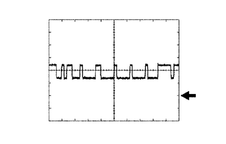
| ECM Terminal Name | Between CANL and E1 |
| Tester Range | 1 V/DIV., 10 μs./DIV. |
| Condition | Engine stopped, ignition switch ON |
- HINT:
-
The waveform varies depending on the CAN communication signal.
WAVEFORM 3
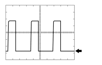
| ECM Terminal Name | Between NEO and E1 |
| Tester Range | 2 V/DIV., 2 ms./DIV. |
| Condition | Idling with warm engine |
- HINT:
-
The wavelength becomes shorter as the engine speed increases.
WAVEFORM 4
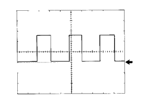
| ECM Terminal Name | Between SPD and E1 |
| Tester Range | 2 V/DIV., 20 ms./DIV. |
| Condition | Driving at 20 km/h (12 mph) |
- HINT:
-
The wavelength becomes shorter as the vehicle speed increases.
WAVEFORM 5
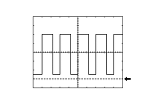
| ECM Terminal Name | Between RFC and E1 |
| Tester Range | 1 V/DIV., 2 ms./DIV. |
| Condition | Ignition switch ON, A/C switch on (max cool) |
- HINT:
-
The duty ratio varies depending on the engine coolant temperature.
WAVEFORM 6
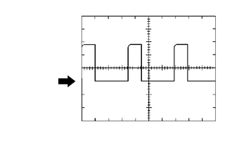
| ECM Terminal Name | Between OC1+ and OC1- |
| Tester Range | 5 V/DIV., 1 ms./DIV. |
| Condition | Idling |
WAVEFORM 7
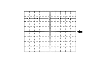
| ECM Terminal Name | Between M+ and ME01 |
| Tester Range | 5 V/DIV., 1 ms./DIV. |
| Condition | Idling with warm engine |
- HINT:
-
The duty ratio varies depending on the throttle actuator operation.
WAVEFORM 8
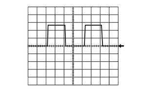
| ECM Terminal Name | Between HA1A and E1 |
| Tester Range | 5 V/DIV., 10 ms./DIV. |
| Condition | Idling with cold engine |
WAVEFORM 9
| ECM Terminal Name | Between OE1+ and OE1- |
| Tester Range | 5 V/DIV., 1 ms./DIV. |
| Condition | Idling |
WAVEFORM 10
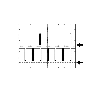
| ECM Terminal Name | CH1: Between IGT (1 to 4) and E1
CH2: Between IGF1 and E1 |
| Tester Range | 2 V/DIV., 20 ms./DIV. |
| Condition | Idling with warm engine |
- HINT:
-
The wavelength becomes shorter as the engine speed increases.
WAVEFORM 11
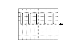
| ECM Terminal Name | Between M- and ME01 |
| Tester Range | 5 V/DIV., 1 ms./DIV. |
| Condition | Idling with warm engine |
- HINT:
-
The duty ratio varies depending on the throttle actuator operation.
WAVEFORM 12
| ECM Terminal Name | Between HA1B and E1 |
| Tester Range | 5 V/DIV., 10 ms./DIV. |
| Condition | Idling with cold engine |
WAVEFORM 13
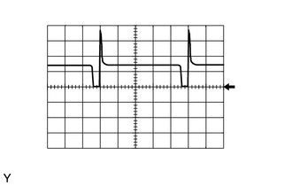
| ECM Terminal Name | Between PRG and E1 |
| Tester Range | 10 V/DIV., 20 ms./DIV. |
| Condition | Idling with warm engine, under purge control |
- HINT:
-
If the waveform is not similar to the illustration, check the waveform again after idling for 10 minutes or more.
WAVEFORM 14
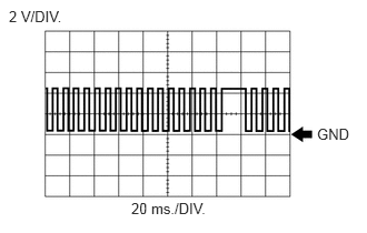
| ECM Terminal Name | Between NE+ and NE- |
| Tester Range | 2 V/DIV., 20 ms./DIV. |
| Condition | Idling with warm engine |
- HINT:
-
The wavelength becomes shorter as the engine speed increases.
WAVEFORM 15
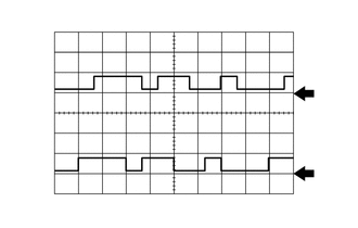
| ECM Terminal Name | CH1: Between VV1+ and VV1-
CH2: Between EV1+ and EV1- |
| Tester Range | 5 V/DIV., 20 ms./DIV. |
| Condition | Idling with warm engine |
- HINT:
-
The wavelength becomes shorter as the engine speed increases.
WAVEFORM 16
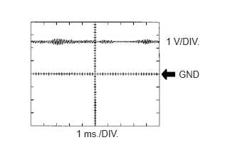
| ECM Terminal Name | Between KNK1 and EKNK |
| Tester Range | 1 V/DIV., 1 ms./DIV. |
| Condition | Engine speed maintained at 4000 rpm after warming up engine |
- HINT:
- ·
The wavelength becomes shorter as the engine speed increases.
·The waveforms and amplitudes displayed will differ slightly depending on the vehicle.