RM3660EC _56 Audio / Visual / Telematics _080751 AUDIO / VIDEO _0599626 AUDIO AND VISUAL SYSTEM(for 10.25 Inch Display) J

AUDIO / VIDEO  AUDIO AND VISUAL SYSTEM(for 10.25 Inch Display)  USB Audio System Recognition/Play Error  


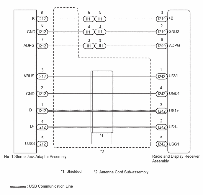
WIRING DIAGRAM
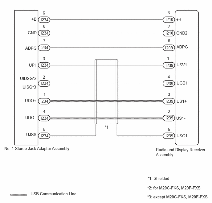
for GTMC Made
E500782E48
5.594,0.573 5.938,0.823 0.344,0.25 10 false I210 5.594,1.031 5.958,1.271 0.365,0.24 10 false I210 5.583,1.531 5.885,1.75 0.302,0.219 10 false I209 5.594,2.125 5.906,2.385 0.313,0.26 10 false I239 1.375,4.5 1.823,4.802 0.448,0.302 10 false I234 1.375,3.906 1.792,4.146 0.417,0.24 10 false I234 1.365,3.333 1.875,3.583 0.51,0.25 10 false I234 1.375,2.729 1.75,2.969 0.375,0.24 10 false I234 1.375,2.115 1.771,2.375 0.396,0.26 10 false I234 1.365,1.521 1.927,1.729 0.563,0.208 10 false I234 1.375,1.031 1.729,1.219 0.354,0.188 10 false I234 1.375,0.583 1.677,0.813 0.302,0.229 10 false I234 5.271,4.969 6.948,5.396 1.677,0.427 10 false Radio and Display Receiver Assembly 0.958,6.458 2.656,6.635 1.698,0.177 10 false : USB Communication Line 0.146,4.927 2.51,5.396 2.365,0.469 10 false No. 1 Stereo Jack Adapter Assembly 4.979,6.26 7,6.542 2.021,0.281 10 false *2: for M20C-FKS, M20F-FXS 5.667,0.344 5.833,0.552 0.167,0.208 10 false 3 5.667,0.813 5.823,1.021 0.156,0.208 10 false 2 5.677,1.292 5.823,1.49 0.146,0.198 10 false 6 5.646,1.885 5.792,2.083 0.146,0.198 10 false 1 1.448,2.521 1.615,2.75 0.167,0.229 10 false 2 5.677,3.104 5.865,3.313 0.188,0.208 10 false 3 5.677,3.677 5.823,3.865 0.146,0.188 10 false 2 5.677,4.281 5.854,4.479 0.177,0.198 10 false 5 3.542,4.208 3.802,4.396 0.26,0.188 10 false *1 1.448,0.354 1.604,0.552 0.156,0.198 10 false 6 1.458,0.802 1.833,1 0.375,0.198 10 false 8 1.458,1.292 1.615,1.49 0.156,0.198 10 false 7 1.448,1.896 1.615,2.094 0.167,0.198 10 false 3 5.667,2.51 5.833,2.719 0.167,0.208 10 false 4 1.469,3.115 1.604,3.323 0.135,0.208 10 false 1 1.458,3.677 1.625,3.885 0.167,0.208 10 false 4 1.458,4.281 1.594,4.479 0.135,0.198 10 false 5 5.958,0.573 6.208,0.76 0.25,0.188 10 false +B 1.063,0.563 1.344,0.76 0.281,0.198 10 false +B 0.938,1.021 1.396,1.219 0.458,0.198 10 false GND 5.958,1.031 6.417,1.229 0.458,0.198 10 false GND2 5.969,1.5 6.427,1.698 0.458,0.198 10 false ADPG 5.969,2.104 6.427,2.302 0.458,0.198 10 false USV1 5.969,2.719 6.427,2.917 0.458,0.198 10 false UGD1 5.969,3.333 6.427,3.531 0.458,0.198 10 false US1+ 5.958,3.906 6.417,4.104 0.458,0.198 10 false US1- 5.969,4.5 6.427,4.698 0.458,0.198 10 false USG1 0.885,4.458 1.281,4.625 0.396,0.167 10 false UJSS 0.854,3.885 1.313,4.083 0.458,0.198 10 false UDO- 0.844,3.313 1.302,3.51 0.458,0.198 10 false UDO+ 0.677,2.563 1.323,2.781 0.646,0.219 10 false UIDSG*2 0.979,2.115 1.385,2.313 0.406,0.198 10 false UPI 0.854,1.542 1.313,1.74 0.458,0.198 10 false ADPG 5.594,2.74 5.906,3 0.313,0.26 10 false I239 5.594,3.333 5.906,3.594 0.313,0.26 10 false I239 5.594,3.896 5.906,4.156 0.313,0.26 10 false I239 5.594,4.5 5.906,4.76 0.313,0.26 10 false I239 0.76,2.854 1.292,3.052 0.531,0.198 10 false UISG*3 4.979,6.563 7.156,6.802 2.177,0.24 10 false *3: except M20C-FKS, M20F-FXS 4.99,5.938 6.406,6.219 1.417,0.281 10 false *1: Shielded

for TFTM Made
E500781E13
5.583,0.573 5.875,0.781 0.292,0.208 10 false I210 5.573,2.604 5.99,2.896 0.417,0.292 10 false I242 5.573,3.208 6.083,3.479 0.51,0.271 10 false I242 5.583,3.823 6,4.104 0.417,0.281 10 false I242 5.583,4.385 6.042,4.656 0.458,0.271 10 false I242 5.573,4.979 6.021,5.281 0.448,0.302 10 false I242 1.354,4.979 1.823,5.26 0.469,0.281 10 false I212 1.354,4.385 1.906,4.573 0.552,0.188 10 false I212 1.365,3.813 1.906,4.063 0.542,0.25 10 false I212 1.365,3.208 1.875,3.427 0.51,0.219 10 false I212 1.354,2.604 1.906,2.844 0.552,0.24 10 false I212 1.365,1.531 1.854,1.792 0.49,0.26 10 false I212 1.365,1.031 1.802,1.302 0.438,0.271 10 false I212 1.354,0.573 1.771,0.844 0.417,0.271 10 false I212 5.375,5.406 7.063,5.865 1.688,0.458 10 false Radio and Display Receiver Assembly 0.948,6.458 2.656,6.656 1.708,0.198 10 false : USB Communication Line 0.146,5.417 3.188,5.688 3.042,0.271 10 false No. 1 Stereo Jack Adapter Assembly 2.146,5.938 3.563,6.219 1.417,0.281 10 false *1: Shielded 3.313,5.958 6.938,6.188 3.625,0.229 10 false *2: Antenna Cord Sub-assembly 3.469,0.583 3.875,0.823 0.406,0.24 10 false II1 3.469,1.031 3.958,1.24 0.49,0.208 10 false II1 3.49,1.521 3.906,1.74 0.417,0.219 10 false II1 3.063,1.531 3.51,1.75 0.448,0.219 10 false II1 3.042,1.042 3.469,1.25 0.427,0.208 10 false II1 3.042,0.583 3.458,0.854 0.417,0.271 10 false II1 5.677,0.354 5.854,0.542 0.177,0.188 10 false 3 5.667,0.823 5.802,1.021 0.135,0.198 10 false 2 5.677,1.302 5.854,1.521 0.177,0.219 10 false 6 5.646,2.365 5.813,2.573 0.167,0.208 10 false 1 1.448,3 1.625,3.208 0.177,0.208 10 false 2 5.656,3.594 5.813,3.802 0.156,0.208 10 false 3 5.656,4.167 5.802,4.344 0.146,0.177 10 false 2 5.656,4.76 5.823,4.938 0.167,0.177 10 false 5 3.104,0.354 3.271,0.563 0.167,0.208 10 false 5 3.5,0.344 3.688,0.531 0.188,0.188 10 false 5 3.5,0.854 3.656,1.042 0.156,0.188 10 false 4 3.104,0.854 3.25,1.073 0.146,0.219 10 false 4 3.104,1.333 3.281,1.531 0.177,0.198 10 false 3 3.49,1.344 3.656,1.542 0.167,0.198 10 false 3 3.521,4.688 3.74,4.885 0.219,0.198 10 false *1 3.542,5.24 4.323,5.594 0.781,0.354 10 false *2 1.448,0.365 1.615,0.594 0.167,0.229 10 false 6 1.458,0.802 1.833,1 0.375,0.198 10 false 8 1.458,1.302 1.635,1.531 0.177,0.229 10 false 7 1.458,2.375 1.833,2.573 0.375,0.198 10 false 3 5.646,3 5.813,3.208 0.167,0.208 10 false 4 1.448,3.594 1.823,3.792 0.375,0.198 10 false 1 1.458,4.177 1.833,4.375 0.375,0.198 10 false 4 1.458,4.76 1.635,5 0.177,0.24 10 false 5 5.948,0.552 6.177,0.74 0.229,0.188 10 false +B 1.052,0.573 1.302,0.771 0.25,0.198 10 false +B 0.948,1.031 1.406,1.229 0.458,0.198 10 false GND 5.948,1.021 6.406,1.219 0.458,0.198 10 false GND2 5.969,1.51 6.427,1.708 0.458,0.198 10 false ADPG 5.958,2.583 6.417,2.781 0.458,0.198 10 false USV1 5.969,3.198 6.427,3.396 0.458,0.198 10 false UGD1 5.969,3.802 6.427,4 0.458,0.198 10 false US1+ 5.958,4.375 6.417,4.573 0.458,0.198 10 false US1- 5.958,4.979 6.417,5.177 0.458,0.198 10 false USG1 0.885,4.958 1.344,5.156 0.458,0.198 10 false UJSS 1.063,4.354 1.521,4.552 0.458,0.198 10 false D- 1.031,3.781 1.49,3.979 0.458,0.198 10 false D+ 0.917,3.208 1.375,3.406 0.458,0.198 10 false GND 0.844,2.583 1.302,2.781 0.458,0.198 10 false VBUS 0.833,1.51 1.292,1.708 0.458,0.198 10 false ADPG 5.583,1.031 5.875,1.24 0.292,0.208 10 false I210 5.583,1.521 5.875,1.729 0.292,0.208 10 false I209

CAUTION / NOTICE / HINT

NOTICE:

Depending on the parts that are replaced during vehicle inspection or maintenance, performing initialization, registration or calibration may be needed.

Click hereAudio / Visual / Telematics>AUDIO / VIDEO>AUDIO AND VISUAL SYSTEM (for 10.25 Inch Display)>PRECAUTION


HINT:
·

When many folders or files exist in the USB storage device, it may take a while to begin playback.

·

When using a USB storage device, files that are protected by copyright or encrypted cannot be played

·

If a USB hub is being used, remove it.

·

When files on the USB storage device are not played in the sorted order, perform the following procedure.

(a)

Assign a number to the start of each file name.

(b)

Move the files to a folder and copy each folder to the USB storage device.


PROCEDURE

1.CHECK USB STORAGE DEVICE OR "iPod"
a.

Disconnect the USB storage device or "iPod" from the No.1 stereo jack adapter assembly.


b.

Check that playable files exist in the USB storage device or "iPod".


c.

Check that the USB storage device or "iPod" being used by the customer is a compatible version and format.


Result:
Result Proceed to
The format of the USB storage device is compatible
The version of the "iPod" is compatible
(for GTMC Made)
A
The format of the USB storage device is compatible
The version of the "iPod" is compatible
(for TFTM Made)
B
Playable files do not exist
The format of the USB storage device is not compatible
The version of the "iPod" is not compatible
C


A

2.CHECK HARNESS AND CONNECTOR (RADIO AND DISPLAY RECEIVER ASSEMBLY - NO. 1 STEREO JACK ADAPTER ASSEMBLY)

B

7.INSPECT ANTENNA CORD SUB-ASSEMBLY

C

END

2.CHECK HARNESS AND CONNECTOR (RADIO AND DISPLAY RECEIVER ASSEMBLY - NO. 1 STEREO JACK ADAPTER ASSEMBLY)
a.

Disconnect the I209, I239 radio and display receiver assembly connectors.


b.

Disconnect the I234 No. 1 stereo jack adapter assembly connector.


c.

Measure the resistance according to the value(s) in the table below.

Standard Resistance:
Tester Connection Condition Specified Condition

*1: except M20C-FKS, M20F-FXS

*2: except M20C-FKS, M20F-FXS

I239-1 (USV1) - I234-3 (UPI) Always Below 1 Ω
I239-2 (US1-) - I234-4 (UDO-) Always Below 1 Ω
I239-3 (US1+) - I234-1 (UDO+) Always Below 1 Ω
I239-4 (UGD1) - I234-2 (UIDSG*1, UISG*2) Always Below 1 Ω
I239-5 (USG1) - I234-5 (UJSS) Always Below 1 Ω
I210-3 (+B) - I234-6 (+B) Always Below 1 Ω
I210-2 (GND2) - I234-8 (GND) Always Below 1 Ω
I209-6 (ADPG) - I234-7 (ADPG) Always Below 1 Ω
I239-1 (USV1) or I234-3 (UPI) - Body ground Always 10 kΩ or higher
I239-2 (US1-) or I234-4 (UDO-) - Body ground Always 10 kΩ or higher
I239-3 (US1+) or I234-1 (UDO+) - Body ground Always 10 kΩ or higher
I239-4 (UGD1) or I234-2 (UIDSG*1, UISG*2) - Body ground Always 10 kΩ or higher
I239-5 (USG1) or I234-5 (UJSS) - Body ground Always 10 kΩ or higher
I210-3 (+B) or I234-6 (+B) - Body ground Always 10 kΩ or higher
I210-2 (GND2) or I234-8 (GND) - Body ground Always 10 kΩ or higher
I209-6 (ADPG) or I234-7 (ADPG) - Body ground Always 10 kΩ or higher


Result:
Proceed to
OK
NG


OK

3.INSPECT RADIO AND DISPLAY RECEIVER ASSEMBLY (USV1, +B)

NG

REPAIR OR REPLACE HARNESS OR CONNECTOR

3.INSPECT RADIO AND DISPLAY RECEIVER ASSEMBLY (USV1, +B)
a.

Disconnect the I234 No. 1 stereo jack adapter assembly connector.


b.

Measure the voltage according to the value(s) in the table below.

Standard Voltage:
Tester Connection Condition Specified Condition

*1: for M20C-FKS, M20F-FXS

*2: except M20C-FKS, M20F-FXS

I234-3 (UPI) - I234-2 (UIDSG*1, UISG*2) Ignition switch ON 4.5 to 5.5 V
I234-6 (+B) - I234-8 (GND) Always 11 to 14 V


HINT:

Measure the voltage with the radio and display receiver assembly connectors connected.


Result:
Proceed to
OK
NG


OK

4.FORMAT USB DEVICE OR INITIALIZE "iPod" AND RECHECK

NG

4.FORMAT USB DEVICE OR INITIALIZE "iPod" AND RECHECK
a.

Format the USB storage device or initialize the "iPod" to delete the audio files.

NOTICE:

When formatting the USB storage device or initializing the "iPod", all audio files stored in the device will be deleted. Make sure to back up the audio files before performing this procedure.


b.

Restore the data and check if the problem can be reproduced.


Result:
Result Proceed to
Malfunction disappears A
Malfunction occurs. B


A

END

B

5.CHECK USB STORAGE DEVICE OR "iPod'"
a.

Disconnect the USB storage device or "iPod" from the No. 1 stereo jack adapter assembly.


b.

Turn the ignition switch from off to ON

HINT:

If another USB storage device or "iPod" is to be connected, it is necessary to turn the ignition switch off in order for the device to be detected.


c.

Connect a known good USB storage device or "iPod" to the No. 1 stereo jack adapter assembly.

HINT:
·

When a USB storage device is used, replace it with another device and perform the inspection.

·

When an "iPod" is used, replace it with another device and perform the inspection.


d.

Perform the operation again and check if the problem symptom recurs.


Result:
Result Proceed to
Malfunction disappears A
Malfunction occurs B


A

END

B

6.CHECK NO. 1 STEREO JACK ADAPTER ASSEMBLY
a.

Replace the No.1 stereo jack adapter assembly with a new or known good one.

Click hereAudio / Visual / Telematics>AUDIO / VIDEO>STEREO JACK ADAPTER ASSEMBLY>REMOVAL


b.

Check if the problem symptom recurs.


Result:
Result Proceed to
Malfunction disappears A
Malfunction occurs B


A

END (NO. 1 STEREO JACK ADAPTER ASSEMBLY MALFUNCTION)

B

7.INSPECT ANTENNA CORD SUB-ASSEMBLY
a.

Disconnect the I242 radio and display receiver assembly connector.


b.

Disconnect the I212 No. 1 stereo jack adapter assembly connector.


c.

Disconnect the II1 antenna cord sub-assembly connector.


d.

Measure the resistance according to the value(s) in the table below.

Standard Resistance:
Tester Connection Condition Specified Condition
I242-1 (USV1) - I212-3 (VBUS) Always Below 1 Ω
I242-2 (US1-) - I212-4 (D-) Always Below 1 Ω
I242-3 (US1+) - I212-1 (D+) Always Below 1 Ω
I242-4 (UGD1) - I212-2 (GND) Always Below 1 Ω
I242-5 (USG1) - I212-5 (UJSS) Always Below 1 Ω
II1-5 - I212-6 (+B) Always Below 1 Ω
II1-4 - I212-8 (GND) Always Below 1 Ω
II1-3 - I212-7 (ADPG) Always Below 1 Ω
I242-1 (USV1) or I212-3 (VBUS) - Body ground Always 10 kΩ or higher
I242-2 (US1-) or I212-4 (D-) - Body ground Always 10 kΩ or higher
I242-3 (US1+) or I212-1 (D+) - Body ground Always 10 kΩ or higher
I242-4 (UGD1) or I212-2 (GND) - Body ground Always 10 kΩ or higher
I242-5 (USG1) or I212-5 (UJSS) - Body ground Always 10 kΩ or higher
II1-5 or I212-6 (+B) - Body ground Always 10 kΩ or higher
II1-4 or I212-8 (GND) - Body ground Always 10 kΩ or higher
II1-3 or I212-7 (ADPG) - Body ground Always 10 kΩ or higher


Result:
Proceed to
OK
NG


OK

8.CHECK HARNESS AND CONNECTOR (ANTENNA CORD SUB-ASSEMBLY - RADIO AND DISPLAY RECEIVER ASSEMBLY)

NG

8.CHECK HARNESS AND CONNECTOR (ANTENNA CORD SUB-ASSEMBLY - RADIO AND DISPLAY RECEIVER ASSEMBLY)
a.

Disconnect the II1 antenna cord sub-assembly connector.


b.

Disconnect the I209, I210 radio and display receiver assembly connectors.


c.

Measure the resistance according to the value(s) in the table below.

Standard Resistance:
Tester Connection Condition Specified Condition
II1-5 - I210-3 (+B) Always Below 1 Ω
II1-4 - I210-2 (GND2) Always Below 1 Ω
II1-3 - I209-6 (ADPG) Always Below 1 Ω
II1-5 or I210-3 (+B) - Body ground Always 10 kΩ or higher
II1-4 or I210-2 (GND2) - Body ground Always 10 kΩ or higher
II1-3 or I209-6 (ADPG) - Body ground Always 10 kΩ or higher


Result:
Proceed to
OK
NG


OK

9.INSPECT RADIO AND DISPLAY RECEIVER ASSEMBLY (USV1, +B)

NG

REPAIR OR REPLACE HARNESS OR CONNECTOR

9.INSPECT RADIO AND DISPLAY RECEIVER ASSEMBLY (USV1, +B)
a.

Disconnect the I212 No. 1 stereo jack adapter assembly connector.


b.

Measure the voltage according to the value(s) in the table below.

Standard Voltage:
Tester Connection Condition Specified Condition
I212-3 (VBUS) - I212-2 (GND) Ignition switch ON 4.5 to 5.5 V
I212-6 (+B) - I212-8 (GND) Always 11 to 14 V


HINT:

Measure the voltage with the radio and display receiver assembly connectors connected.


Result:
Proceed to
OK
NG


OK

10.FORMAT USB DEVICE OR INITIALIZE "iPod" AND RECHECK

NG

10.FORMAT USB DEVICE OR INITIALIZE "iPod" AND RECHECK
a.

Format the USB storage device or initialize the "iPod" to delete the audio files.

NOTICE:

When formatting the USB storage device or initializing the "iPod", all audio files stored in the device will be deleted. Make sure to back up the audio files before performing this procedure.


b.

Restore the data and check if the problem can be reproduced.


Result:
Result Proceed to
Malfunction disappears A
Malfunction occurs. B


A

END

B

11.CHECK USB STORAGE DEVICE OR "iPod'"
a.

Disconnect the USB storage device or "iPod" from the No. 1 stereo jack adapter assembly.


b.

Turn the ignition switch from off to ON

HINT:

If another USB storage device or "iPod" is to be connected, it is necessary to turn the ignition switch off in order for the device to be detected.


c.

Connect a known good USB storage device or "iPod" to the No. 1 stereo jack adapter assembly.

HINT:
·

When a USB storage device is used, replace it with another device and perform the inspection.

·

When an "iPod" is used, replace it with another device and perform the inspection.


d.

Perform the operation again and check if the problem symptom recurs.


Result:
Result Proceed to
Malfunction disappears A
Malfunction occurs B


A

END

B

12.CHECK NO. 1 STEREO JACK ADAPTER ASSEMBLY
a.

Replace the No.1 stereo jack adapter assembly with a new or known good one.

Click hereAudio / Visual / Telematics>AUDIO / VIDEO>STEREO JACK ADAPTER ASSEMBLY>REMOVAL


b.

Check if the problem symptom recurs.


Result:
Result Proceed to
Malfunction disappears A
Malfunction occurs B


A

END (NO. 1 STEREO JACK ADAPTER ASSEMBLY MALFUNCTION)

B