THEFT DETERRENT / KEYLESS ENTRY ELECTRICAL KEY OSCILLATOR(for Front Floor) REMOVAL
CAUTION / NOTICE / HINT
The necessary procedures (adjustment, calibration, initialization or registration) that must be performed after parts are removed and installed, or replaced during No. 1 indoor electrical key antenna assembly removal/installation are shown below.
- NOTICE:
- ·
After the ignition switch is turned off, the navigation receiver assembly records various types of memory and settings. As a result, after turning the ignition switch off, make sure to wait at least 2 minutes before disconnecting the cable from the negative (-) auxiliary battery terminal. (w/o RST Switch (except 10.25 Inch Display))
·After the ignition switch is turned off, the navigation receiver assembly or radio and display receiver assembly records various types of memory and settings. As a result, after turning the ignition switch off, make sure to wait at least 1 minutes before disconnecting the cable from the negative (-) auxiliary battery terminal. (for 10.25 Inch Display)
·When the cable is disconnected from the negative (-) auxiliary battery terminal and the security lock setting has been enabled, multi-display operations will be disabled upon next startup unless the password is entered. Be sure to check the security lock setting before disconnecting the cable from the negative (-) auxiliary battery terminal. (for 10.25 Inch Display)
- HINT:
-
When the cable is disconnected / reconnected to the battery terminal, systems temporarily stop operating. However, each system has a function that completes learning the first time the system is used.
Learning completes when vehicle is driven Effect/Inoperative Function when Necessary Procedure not Performed Necessary Procedures Link Stop and Start System Idle the engine for approximately 5 to 60 minutes or drive the vehicle until stop and start control is permitted (  201906,999999,_51,_080774,_0393362,RM100000001HXHC,)
Pre-collision System Perform steering sensor zero point calibration ( 202304,999999,_95,_139716,_0601175,RM100000002BFOE,)
Lane Tracing Assist System Front Camera System Drive the vehicle straight ahead at 15 km/h (9 mph) or more for 1 second or more. ( 202304,999999,_95,_139716,_0584193,RM1000000029F4C,)
Learning completes when vehicle is driven Effect/Inoperative Function when Necessary Procedure not Performed Necessary Procedures Link Front Camera System Drive the vehicle straight ahead at 15 km/h (9 mph) or more for 1 second or more. ( 202304,999999,_95,_139716,_0584193,RM1000000029F4C,)
PROCEDURE

 1. PRECAUTION
- NOTICE:
-
After turning the ignition switch (for Gasoline Model) or power switch (for HV Model) off, waiting time may be required before disconnecting the cable from the negative (-) auxiliary battery terminal. Therefore, make sure to read the disconnecting the cable from the negative (-) auxiliary battery terminal notices before proceeding with work.
2.DISCONNECT CABLE FROM NEGATIVE AUXILIARY BATTERY TERMINAL
for NR Series Engine: Click hereGeneral>MAINTENANCE>NR Series BATTERY>REMOVAL202304,999999,_V1,_080956,_0392375,RM100000002BCCL_05_0005,
for 8ZR-FXE: Click hereGeneral>MAINTENANCE>8ZR-FXE AUXILIARY BATTERY>REMOVAL202304,999999,_V1,_080956,_0392376,RM100000002ACL7_01_0028,
for M15B-FKS: Click hereGeneral>MAINTENANCE>M15B-FKS BATTERY>REMOVAL202304,999999,_V1,_080956,_0453685,RM100000002ACNG_05_0005,
for M15C-FKS: Click hereGeneral>MAINTENANCE>M15C-FKS BATTERY>REMOVAL202304,999999,_V1,_080956,_0453686,RM100000002ACNH_05_0005,
for M20A-FKS: Click hereGeneral>MAINTENANCE>M20A-FKS BATTERY>REMOVAL202304,999999,_V1,_080956,_0470107,RM100000002ACOV_05_0005,
for M20E-FKS: Click hereGeneral>MAINTENANCE>M20E-FKS BATTERY>REMOVAL202304,999999,_V1,_080956,_0474497,RM100000002ACOX_05_0005,
for M20C-FKS: Click hereGeneral>MAINTENANCE>M20C-FKS BATTERY>REMOVAL202304,999999,_V1,_080956,_0484846,RM100000002ACOW_05_0005,
55606
3.REMOVE NO. 1 INSTRUMENT PANEL UNDER COVER SUB-ASSEMBLY
55434F
4.REMOVE LOWER CENTER INSTRUMENT PANEL FINISH PANEL
58831A
5.REMOVE FRONT CONSOLE UPPER PANEL GARNISH
33504F
6.REMOVE SHIFT LEVER KNOB SUB-ASSEMBLY (for CVT)
for K313: Click hereDrivetrain>K313 (CVT)>SHIFT LEVER KNOB>REMOVAL201906,999999,_52,_080728,_0392276,RM100000001HPBQ_01_0001,
for K320: Click hereDrivetrain>K320 / K321 (CVT)>SHIFT LEVER KNOB>REMOVAL202101,999999,_52,_096216,_0452233,RM100000001SUD2_01_0001,
for K120: Click hereDrivetrain>K120 / K121 (CVT)>SHIFT LEVER KNOB>REMOVAL202104,999999,_52,_101162,_0469771,RM100000001VJMR_01_0001,
33504F
7.REMOVE SHIFT LEVER KNOB SUB-ASSEMBLY (for HV Model)
35970F
8.REMOVE POSITION INDICATOR HOUSING ASSEMBLY
9.REMOVE CONSOLE CUP HOLDER BOX SUB-ASSEMBLY
899A0
10.REMOVE NO. 1 INDOOR ELECTRICAL KEY ANTENNA ASSEMBLY
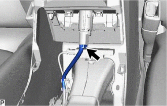
Disconnect the connector.
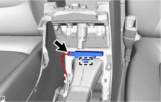
Disconnect the connector.
Disengage the clamp to remove the No. 1 indoor electrical key antenna assembly.
- NOTICE:
-
Be careful when removing the No. 1 indoor electrical key antenna assembly. If the No. 1 indoor electrical key antenna assembly is dropped, replace it with a new one.