THEFT DETERRENT / KEYLESS ENTRY DIGITAL KEY SYSTEM B27C087 Digital Key System Missing Message
DESCRIPTION
This DTC is output when response frames from the digital key ECU assembly were not received 7 times consecutively x 7 sets after UART communication was established.
Also, communication is not possible between the digital key ECU and certification ECU (smart key ECU assembly) when the OTA function used by the digital key is operating. Therefore, when the OTA function is operating due to a digital key operation, etc., and communication between the certification ECU (smart key ECU assembly) and digital key ECU is not possible, this DTC is stored.
| DTC No. | Detection Item | DTC Detection Condition | Trouble Area | DTC Output from | Priority | Note |
|---|---|---|---|---|---|---|
| B27C087 | Digital Key System Missing Message | Output when response frames from the digital key ECU assembly were not received 7 times consecutively x 7 sets after UART communication was established
Also, when communication is not possible between the digital key ECU and certification ECU (smart key ECU assembly) when the OTA function used by the digital key is operating. Therefore, when the OTA function is operating due to a digital key operation, etc., and the certification ECU (smart key ECU assembly) sends a signal to the digital key ECU, communication is not possible and this DTC is stored. |
·
Certification ECU (smart key ECU assembly) ·
Digital key ECU assembly ·
Wire harness or connector |
Entry&Start | A | DTC Output Confirmation Operation:
Any time |
| Vehicle Condition when Malfunction Detected | Fail-safe Operation when Malfunction Detected |
|---|---|
| Digital key system does not operate | - |
WIRING DIAGRAM
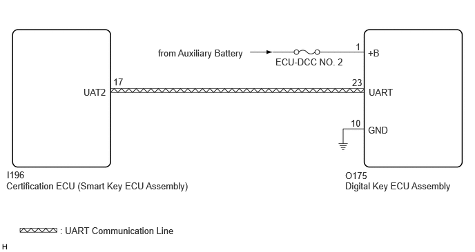
CAUTION / NOTICE / HINT
- NOTICE:
- ·
Before replacing certification ECU (smart key ECU assembly) or digital key ECU assembly, refer to Service Bulletin.
·Inspect the fuses for circuits related to this system before performing the following procedure.
PROCEDURE
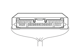
| *a | Component with harness connected
(Digital key ECU Assembly) |
Measure the voltage according to the value(s) in the table below.
- Standard Voltage:
Tester Connection Condition Specified Condition O175-1 (+B) - Body ground Ignition switch off 11 to 14 V
- Result:
Proceed to OK NG
OK
NG
Pre-procedure1
Disconnect the I196 certification ECU (smart key ECU assembly) connector.
Disconnect the O175 digital key ECU connector.
Procedure1
Measure the resistance according to the value(s) in the table below.
- Standard Resistance:
Tester Connection Condition Specified Condition I196-17 (UAT2) - O175-23 (UART) Always Below 1 Ω I196-17 (UAT2) or O175-23 (UART) - Other terminals and body ground Always 10 kΩ or higher O175-10 (GND) - Body ground Always Below 1 Ω
- Result:
Proceed to OK NG
Post-procedure1
Connect the I196 certification ECU (smart key ECU assembly) connector.
OK
NG
Check the digital key application operation history and check if there is OTA function history.
- HINT:
-
Refer to operation history of the digital key application
- Result:
Result Proceed to There is OTA function history A There is no OTA function history B
A
- HINT:
-
The following may be the cause:
- ·
Communication between the certification ECU (smart key ECU assembly) and digital key ECU could not be performed as the OTA function was operating.
B
Clear the DTCs.
- Body Electrical > Entry&Start > Clear DTCs
- 50002 440
- Result:
Proceed to NEXT
NEXT
Check for DTCs.
- Body Electrical > Entry&Start > Trouble Codes
- 50001 440
- Result:
Result Proceed to B27C087 is not output A B27C087 is output B
A
B