LIGHTING (INT) LIGHTING SYSTEM(for NR Series Engine) TERMINALS OF ECU
CHECK MAIN BODY ECU (MULTIPLEX NETWORK BODY ECU) AND DRIVER SIDE JUNCTION BLOCK ASSEMBLY
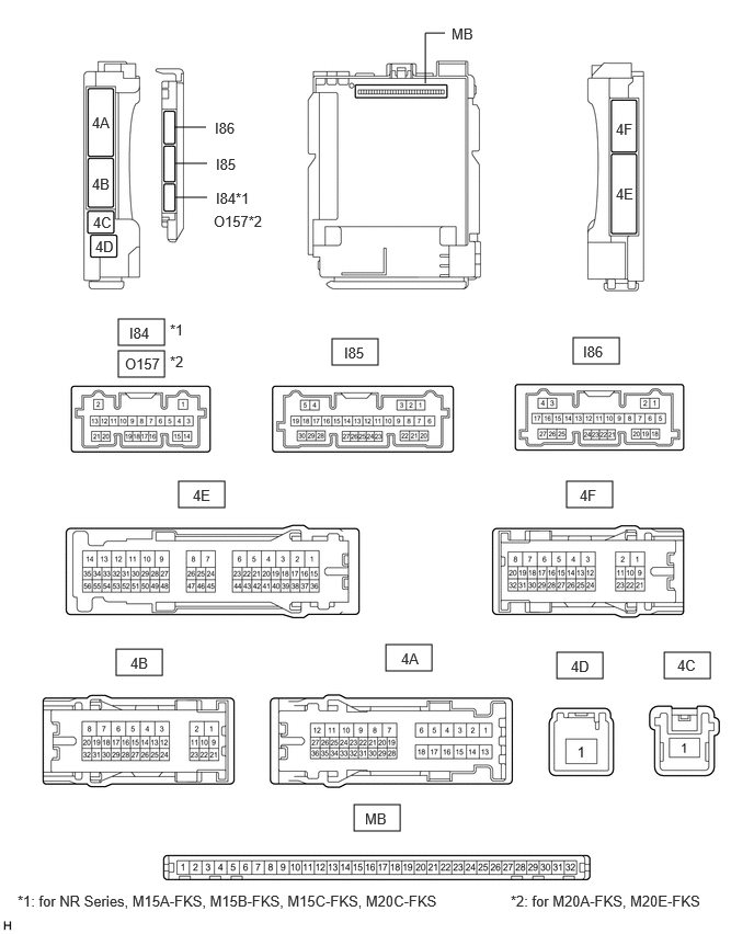
Disconnect the driver side junction block assembly and main body ECU (multiplex network body ECU) connectors.
Measure the voltage and resistance according to the value(s) in the table below.
| Terminal No. (Symbol) | Wiring Color | Terminal Description | Condition | Specified Condition |
|---|---|---|---|---|
| 4F-3 - Body ground | W-B - Body ground | Ground | Always | Below 1 Ω |
| 4B-1 - Body ground | B - Body ground | Battery power supply | Always | 11 to 14 V |
| 4D-1 - Body ground | B-R - Body ground | Battery power supply | Always | 11 to 14 V |
| I86-19 (GND2) - Body ground | W-B - Body ground | Ground | Always | Below 1 Ω |
Connect the driver side junction block assembly and main body ECU (multiplex network body ECU) connectors.
Measure the voltage and check for pulses according to the value(s) in the table below.
| Terminal No. (Symbol) | Wiring Color | Terminal Description | Condition | Specified Condition |
|---|---|---|---|---|
| 4E-17 - Body ground | R - Body ground*1
B - Body ground*2 |
IG power supply | Ignition switch ON | 11 to 14 V |
| Ignition switch off | Below 1 V | |||
| 4E-30 - Body ground | P - Body ground | ACC power supply | Ignition switch ACC | 11 to 14 V |
| Ignition switch off | Below 1 V | |||
| 4E-31 - Body ground | GR - Body ground | Rear door courtesy light switch assembly RH input | Rear door RH open | Below 1 V |
| Rear door RH closed | 11 to 14 V or pulse output (maximum 14 V)*10 | |||
| 4E-36 - Body ground | GR - Body ground | Cup holder light (console box pocket garnish) drive output*5 | Cup holder light (console box pocket garnish) off | 11 to 14 V |
| Cup holder light (console box pocket garnish) at full brightness | Below 2.2 V | |||
| Cup holder light (console box pocket garnish) dimmer control operating (dimming) | Pulse generation | |||
| 4E-37 - Body ground | Y - Body ground*8
B - Body ground*9 |
·
Center tray illumination light (instrument panel light assembly) drive output*6 ·
Footwell light LH (No. 1 interior illumination light assembly) drive output*7 ·
Footwell light RH (No. 1 interior illumination light assembly) drive output*7 |
Center tray illumination light (instrument panel light assembly), footwell light LH (No. 1 interior illumination light assembly) and footwell light RH (No. 1 interior illumination light assembly) off | 11 to 14 V |
| Center tray illumination light (instrument panel light assembly), footwell light LH (No. 1 interior illumination light assembly) and footwell light RH (No. 1 interior illumination light assembly) at full brightness | Below 2.2 V | |||
| Center tray illumination light (instrument panel light assembly), footwell light LH (No. 1 interior illumination light assembly) and footwell light RH (No. 1 interior illumination light assembly) dimmer control operating (dimming) | Pulse generation | |||
| 4F-10 - Body ground | R - Body ground | Map light assembly, rear room light (No. 1 room light assembly)*3 and room light assembly*4 power supply | DOME CUT relay on | 11 to 14 V |
| DOME CUT relay off | Below 1 V | |||
| 4F-12 - Body ground | BR - Body ground | Front door unlock detection switch RH input | Front door RH locked | 11 to 14 V or pulse output (maximum 14 V)*10 |
| Front door RH unlocked | Below 1 V | |||
| 4F-13 - Body ground | SB - Body ground | Front door unlock detection switch LH input | Front door LH locked | 11 to 14 V or pulse output (maximum 14 V)*10 |
| Front door LH unlocked | Below 1 V | |||
| 4F-14 - Body ground | GR - Body ground | Rear door unlock detection switch input | Rear door locked | 11 to 14 V or pulse output (maximum 14 V)*10 |
| Rear door unlocked | Below 1 V | |||
| 4F-24 - Body ground*8 | Y - Body ground | Footwell light RH (No. 1 interior illumination light assembly) power supply*7 | Ignition switch off | 11 to 14 V |
| 4F-24 - Body ground*9 | Y - Body ground | Footwell light LH (No. 1 interior illumination light assembly) power supply*7 | Ignition switch off | 11 to 14 V |
| 4F-25 - Body ground | LG - Body ground | Center tray illumination light (instrument panel light assembly) power supply*6 | Ignition switch off | 11 to 14 V |
| 4F-26 - Body ground | W - Body ground | Cup holder light (Console box pocket garnish) power supply*5 | Ignition switch off | 11 to 14 V |
| 4F-27 - Body ground*8 | R - Body ground | Footwell light LH (No. 1 interior illumination light assembly) power supply*7 | Ignition switch off | 11 to 14 V |
| 4F-27 - Body ground*9 | B - Body ground | Footwell light RH (No. 1 interior illumination light assembly) power supply*7 | Ignition switch off | 11 to 14 V |
| 4F-29 - Body ground | V - Body ground | Illuminated entry system drive output | Map light LH and map light RH (map light assembly), rear room light (No. 1 room light assembly)*3, room light LH and room light RH (room light assembly)*4 off (when operated by illuminated entry system) | 11 to 14 V |
| Map light LH and map light RH (map light assembly), rear room light (No. 1 room light assembly)*3, room light LH and room light RH (room light assembly)*4 on (when operated by illuminated entry system) | Below 1 V | |||
| 4A-19 - Body ground | R - Body ground | No. 1 luggage compartment light assembly power supply | DOME CUT relay on | 11 to 14 V |
| DOME CUT relay off | Below 1 V | |||
| 4A-24 - Body ground | BR - Body ground | Rear door courtesy light switch assembly LH input | Rear door LH open | Below 1 V |
| Rear door LH closed | 11 to 14 V or pulse output (maximum 14 V)*10 | |||
| 4A-34 - Body ground | SB - Body ground | Luggage compartment door courtesy light switch (luggage compartment door lock assembly) input | Luggage compartment door open | Below 1 V |
| Luggage compartment door closed | 11 to 14 V or pulse output (maximum 14 V)*10 | |||
| I85-1 (FLCY) - Body ground | BR - Body ground | Front door courtesy light switch assembly LH input | Front door LH open | Below 1 V |
| Front door LH closed | 11 to 14 V or pulse output (maximum 14 V)*10 | |||
| I85-6 (FRCY) - Body ground | SB - Body ground | Front door courtesy light switch assembly RH input | Front door RH open | Below 1 V |
| Front door RH closed | 11 to 14 V or pulse output (maximum 14 V)*10 | |||
| I85-20 (TCYL) - Body ground | Y - Body ground | No. 1 luggage compartment light assembly drive output | No. 1 luggage compartment light assembly off | 11 to 14 V |
| No. 1 luggage compartment light assembly on | Below 1 V |
*1: w/ Smart Entry and Start System
*2: w/o Smart Entry and Start System
*3: w/ Room Light (for Slide Switch Type)
*4: w/ Room Light (for Push Switch Type)
*5: w/ Cup Holder Light
*6: w/ Center Tray Light
*7: w/ Footwell Light
*8: for TFTM Made
*9: for GTMC Made
*10: Differs depending on the vehicle model
CHECK CERTIFICATION ECU (SMART KEY ECU ASSEMBLY) (w/ Smart Entry and Start System)
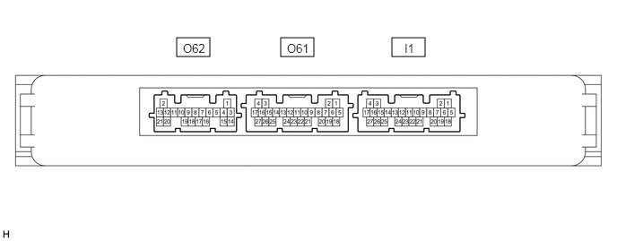
Measure the voltage according to the value(s) in the table below.
| Terminal No. (Symbol) | Wiring Color | Terminal Description | Condition | Specified Condition |
|---|---|---|---|---|
| I1-10 (SWIL) - I1-11 (AGND) | Y - W | Engine switch illumination drive output | Engine switch illumination off | Below 1 V |
| Engine switch illumination on | 11 to 14 V |