TIRE PRESSURE MONITORING TIRE PRESSURE WARNING SYSTEM(for Gasoline Model (for Type A)) TERMINALS OF ECU
CHECK TIRE PRESSURE WARNING ECU AND RECEIVER
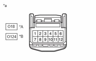
| *A | w/ Smart Entry and Start System |
| *B | w/o Smart Entry and Start System |
| *a | Front view of wire harness connector
(to Tire Pressure Warning ECU and Receiver) |
Disconnect the O18*1, O124*2 tire pressure warning ECU and receiver connector and measure the voltage or resistance on the wire harness side.
*1: w/ Smart Entry and Start System
*2: w/o Smart Entry and Start System
| Terminal No. (Symbol) | Wiring Color | Terminal Description | Condition | Specified Condition |
|---|---|---|---|---|
| O18-1 (IG) - O18-12 (GND) | SB - W-B | IG power source | Ignition switch ON | 10 to 16 V |
| O18-7 (+B) - O18-12 (GND) | BR - W-B | Power supply (from battery) | Always | 10 to 16 V |
| O18-9 (CANH) - O18-10 (CANL) | L - W | CAN communication line | Ignition switch off | 54 to 69 Ω |
| O18-12 (GND) - Body ground | W-B - Body ground | Ground | Always | Below 1 Ω |
| Terminal No. (Symbol) | Wiring Color | Terminal Description | Condition | Specified Condition |
|---|---|---|---|---|
| O124-1 (IG) - O124-12 (GND) | SB - W-B | IG power source | Ignition switch ON | 10 to 16 V |
| O124-7 (+B) - O124-12 (GND) | P - W-B | Power supply (from battery) | Always | 10 to 16 V |
| O124-9 (CANH) - O124-10 (CANL) | L - W | CAN communication line | Ignition switch off | 54 to 69 Ω |
| O124-12 (GND) - Body ground | W-B - Body ground | Ground | Always | Below 1 Ω |
Connect the O18*1 or O124*2 tire pressure warning ECU and receiver connector.
*1: w/ Smart Entry and Start System
*2: w/o Smart Entry and Start System
Measure the voltage according to the value(s) in the table below. If the result is not as specified, the ECU may be malfunctioning.
- HINT:
-
Measure the values on the wire harness side while the connector is connected.

| *A | w/ Smart Entry and Start System | *B | w/o Smart Entry and Start System |
| *a | Component with harness connected
(Tire Pressure Warning ECU and Receiver) |
- | - |
| Terminal No. (Symbol) | Wiring Color | Terminal Description | Condition | Specified Condition |
|---|---|---|---|---|
| O18-3 (CLSW) - O18-12 (GND) | B - W-B | Tire pressure warning reset switch | ·
Ignition switch ON ·
Steering pad switch assembly operated, "Set Pressure" selected on the multi-information display and "OK" switch (steering pad switch assembly) pressed and held |
Below 1.5 V |
·
Ignition switch ON ·
"OK" switch (steering pad switch assembly) off |
8 to 15 V | |||
| O18-4 (RDA) - O18-12 (GND) | LG - W-B | Output signals | Ignition switch ON | Pulse generation (see waveform 1) |
| O18-5 (PRG) - O18-12 (GND) | GR - W-B | Input signals | Ignition switch ON | Pulse generation (see waveform 1) |
| Terminal No. (Symbol) | Wiring Color | Terminal Description | Condition | Specified Condition |
|---|---|---|---|---|
| O124-3 (CLSW) - O124-12 (GND) | B - W-B | Tire pressure warning reset switch | ·
Ignition switch ON ·
Steering pad switch assembly operated, "Set Pressure" selected on the multi-information display and "OK" switch (steering pad switch assembly) pressed and held |
Below 1.5 V |
·
Ignition switch ON ·
"OK" switch (steering pad switch assembly) off |
8 to 15 V | |||
| O124-4 (RDA) - O124-12 (GND) | LG - W-B | Output signals | Ignition switch ON | Pulse generation (see waveform 1) |
| O124-5 (PRG) - O124-12 (GND) | GR - W-B | Input signals | Ignition switch ON | Pulse generation (see waveform 1) |
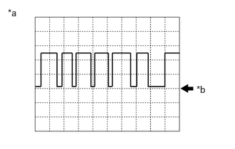
| *a | Example |
| *b | GND |
Using an oscilloscope, check waveform 1.
| Item | Contents |
|---|---|
| Terminal | O18-4 (RDA) - O18-12 (GND)*1
O124-4 (RDA) - O124-12 (GND)*2 O18-5 (PRG) - O18-12 (GND)*1 O124-5 (PRG) - O124-12 (GND)*2 |
| Tool setting | 5 V/DIV, 5 ms./DIV. |
| Vehicle condition | Ignition switch ON |
*1: w/ Smart Entry and Start System
*2: w/o Smart Entry and Start System
- HINT:
-
The waveform shown in the illustration is an example. If the tester displays a waveform that alternates between high and low, where high is a voltage that is between the IG power source voltage and a voltage 2.2 V lower than the IG power source voltage, and where low is a voltage of between 0 and 1.2 V, the ECU can be judged normal.