K313 CVT CONTINUOUSLY VARIABLE TRANSAXLE SYSTEM Transmission Control Switch Circuit
DESCRIPTION
After moving the shift lever to M, it is possible to change the shift range between M1 and M10 using the shift lever. Moving the shift lever to "+" once raises the shift range by one, and moving the shift lever to "-" lowers the shift range by one.
WIRING DIAGRAM
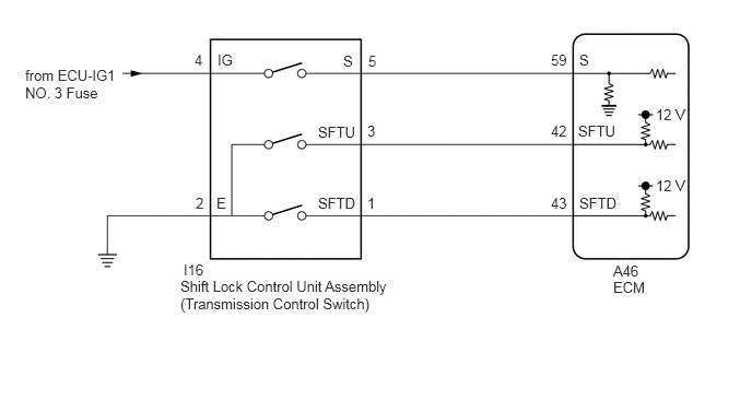
CAUTION / NOTICE / HINT
- NOTICE:
- ·
Perform initialization when parts related to the continuously variable transaxle system are replaced.
·Check that no DTCs are stored after performing initialization.
·Inspect the fuses for circuits related to this system before performing the following procedure.
PROCEDURE
Connect the GTS to the DLC3.
Turn the ignition switch to ON.
Turn the GTS on.
Enter the following menus: Powertrain / Engine / Trouble Codes.
- Powertrain > Engine > Trouble Codes
- 50001 372
Read the DTCs using the GTS.
- Result:
Result Proceed to DTCs are not output A DTCs are output B
A
B
Connect the GTS to the DLC3.
Turn the ignition switch to ON.
Turn the GTS on.
Enter the following menus: Powertrain / Engine / Data List.
According to the display on the GTS, read the Data List.
- Powertrain > Engine > Data List
-
Tester Display Measurement Item Range Normal Condition Diagnostic Note Shift SW Status (S Range) Transmission control switch status ON or OFF ·ON: Shift lever in M, "+" or "-"
·OFF: Shift lever not in M, "+" or "-"
-
- Powertrain > Engine > Data List
-
Tester Display Shift SW Status (S Range) - 50003 372 27
- Result:
Result Proceed to Data List value is normal A Data List value is not normal B
A
B
Connect the GTS to the DLC3.
Turn the ignition switch to ON.
Turn the GTS on.
Enter the following menus: Powertrain / Engine / Data List.
According to the display on the GTS, read the Data List.
- Powertrain > Engine > Data List
-
Tester Display Measurement Item Range Normal Condition Diagnostic Note Sport Shift Up SW Sport shift up switch status ON or OFF ·ON: Shift lever held in "+"
·OFF: Shift lever not held in "+"
- Sport Shift Down SW Sport shift down switch status ON or OFF ·ON: Shift lever held in "-"
·OFF: Shift lever not held in "-"
-
- Powertrain > Engine > Data List
-
Tester Display Sport Shift Up SW Sport Shift Down SW - 50003 372 26,25
- Result:
Result Proceed to Data List values are normal A Data List values are not normal B
A
B

| *a | Component without harness connected
(Shift Lock Control Unit Assembly (Transmission Control Switch)) |
Disconnect the I16 shift lock control unit assembly (transmission control switch) connector.
Measure the resistance according to the value(s) in the table below.
- Standard Resistance:
Tester Connection Condition Specified Condition 3 (SFTU) - 2 (E) Shift lever held in "+" Below 1 Ω 3 (SFTU) - 2 (E) Shift lever in M 10 kΩ or higher 1 (SFTD) - 2 (E) Shift lever held in "-" Below 1 Ω 1 (SFTD) - 2 (E) Shift lever in M 10 kΩ or higher
Connect the I16 shift lock control unit assembly (transmission control switch) connector.
- Result:
Proceed to OK NG
OK
NG
Click hereDrivetrain>K313 (CVT)>SHIFT LEVER>COMPONENTS201906,999999,_52,_080728,_0392275,RM100000001HPBI,
Disconnect the I16 shift lock control unit assembly (transmission control switch) connector.
Measure the resistance according to the value(s) in the table below.
- Standard Resistance:
Tester Connection Condition Specified Condition I16-2 (E) - Body ground Always Below 1 Ω
Connect the I16 shift lock control unit assembly (transmission control switch) connector.
- Result:
Proceed to OK NG
OK
NG
Disconnect the A46 ECM connector.
Measure the resistance according to the value(s) in the table below.
- Standard Resistance:
Tester Connection Condition Specified Condition A46-43 (SFTD) - Body ground Shift lever held in "-" Below 1 Ω A46-43 (SFTD) - Body ground Shift lever in M 10 kΩ or higher A46-42 (SFTU) - Body ground Shift lever held in "+" Below 1 Ω A46-42 (SFTU) - Body ground Shift lever in M 10 kΩ or higher
Connect the A46 ECM connector.
- Result:
Proceed to OK NG
OK
NG
- Result:
Proceed to NEXT
NEXT
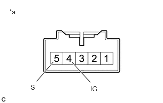
| *a | Component without harness connected
(Shift Lock Control Unit Assembly (Transmission Control Switch)) |
Disconnect the I16 shift lock control unit assembly (transmission control switch) connector.
Measure the resistance according to the value(s) in the table below.
- Standard Resistance:
Tester Connection Condition Specified Condition 4 (IG) - 5 (S) Shift lever in M Below 1 Ω 4 (IG) - 5 (S) Shift lever not in M 10 kΩ or higher
Connect the I16 shift lock control unit assembly (transmission control switch) connector.
- Result:
Proceed to OK NG
OK
NG
Click hereDrivetrain>K313 (CVT)>SHIFT LEVER>COMPONENTS201906,999999,_52,_080728,_0392275,RM100000001HPBI,
Disconnect the I16 shift lock control unit assembly (transmission control switch) connector.
Measure the voltage according to the value(s) in the table below.
- Standard Voltage:
Tester Connection Condition Specified Condition I16-4 (IG) - Body ground Ignition switch ON 11 to 14 V I16-4 (IG) - Body ground Ignition switch off Below 1 V
Connect the I16 shift lock control unit assembly (transmission control switch) connector.
- Result:
Proceed to OK NG
OK
NG
Disconnect the A46 ECM connector.
Disconnect the I16 shift lock control unit assembly (transmission control switch) connector.
Measure the resistance according to the value(s) in the table below.
- Standard Resistance:
Tester Connection Condition Specified Condition I16-5 (S) - A46-59 (S) Always Below 1 Ω I16-5 (S) or A46-59 (S) - Body ground and other terminals Always 10 kΩ or higher
Connect the I16 shift lock control unit assembly (transmission control switch) connector.
Connect the A46 ECM connector.
- Result:
Proceed to OK NG
OK
NG
- Result:
Proceed to NEXT
NEXT