K313 CVT CONTINUOUSLY VARIABLE TRANSAXLE SYSTEM P061512 Starter Relay Circuit Short to Battery
MONITOR DESCRIPTION
While the engine is being cranked, battery voltage is applied to terminal STA of the ECM.
If the ECM detects the starter control (STA) signal while the vehicle is being driven, it determines that there is a malfunction in the STA circuit. The ECM then illuminates the MIL and stores this DTC.
This monitor begins running when the vehicle is driven at 20 km/h (12 mph) or more for 20 seconds.
| DTC No. | Detection Item | DTC Detection Condition | Trouble Area | MIL | Memory | Note |
|---|---|---|---|---|---|---|
| P061512 | Starter Relay Circuit Short to Battery | All of the following conditions are met (1-trip detection logic):
·
The battery voltage is 10.5 V or more. ·
The vehicle speed is 20 km/h (12 mph) or more. ·
The engine speed is more than 1000 rpm. ·
The starter signal is ON for 20 seconds or more. |
·
ST relay ·
Starter signal circuit ·
Park/neutral position switch assembly ·
Certification ECU (Smart key ECU assembly) ·
Engine stop and start ECU ·
ECM |
Comes on | DTC stored | SAE Code:
P0617 |
CONFIRMATION DRIVING PATTERN
- CAUTION:
-
When performing the confirmation driving pattern, obey all speed limits and traffic laws.
- HINT:
- ·
After repairs have been completed, clear the DTCs and then check that the vehicle has returned to normal by performing the following All Readiness check procedure.
·When clearing the permanent DTCs, refer to the Clear Permanent DTC procedure.
Connect the GTS to the DLC3.
Turn the ignition switch to ON and turn the GTS on.
Clear the DTCs (even if no DTCs are stored, perform the clear DTC procedure).
Turn the ignition switch off and wait for 2 minutes or more.
Turn the ignition switch to ON and turn the GTS on.
Start the engine.
Drive the vehicle for 20 seconds or more with the following conditions met [*1]:
Engine speed is 1000 rpm or more.
Vehicle speed is 20 km/h (12 mph) or more.
- HINT:
-
[*1]: Normal judgment procedure.
-
The normal judgment procedure is used to complete DTC judgment and also used when clearing permanent DTCs.
Stop the vehicle.
Enter the following menus: Powertrain / Transmission / Utility / All Readiness.
Input the DTC: P061512.
Check the DTC judgment result.
| GTS Display | Description |
|---|---|
| NORMAL | ·
DTC judgment completed ·
System normal |
| ABNORMAL | ·
DTC judgment completed ·
System abnormal |
| INCOMPLETE | ·
DTC judgment not completed ·
Perform driving pattern after confirming DTC enabling conditions |
| N/A | ·
Unable to perform DTC judgment ·
Number of DTCs which do not fulfill DTC preconditions has reached ECU memory limit |
- HINT:
- ·
If the judgment result shows NORMAL, the system is normal.
·If the judgment result shows ABNORMAL, the system has a malfunction.
·If the judgment result shows INCOMPLETE or N/A, perform the normal judgment procedure again.
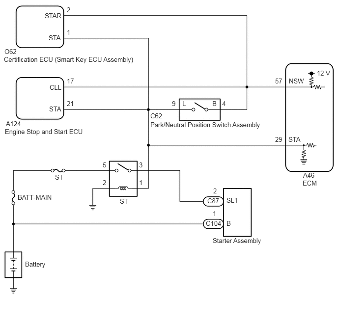
WIRING DIAGRAM
CAUTION / NOTICE / HINT
- CAUTION:
- ·
Strictly observe posted speed limits, traffic laws and road conditions.
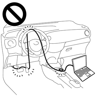
·Do not drive the vehicle with the cable of the GTS contacting the pedals, shift lever or steering wheel.
·Driving the vehicle with the cable of the GTS contacting these areas could impede vehicle control, resulting in a serious accident.
- ·
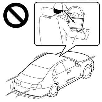
Do not operate the GTS while driving the vehicle.
·Operating the GTS while driving the vehicle will prevent you from paying sufficient attention to vehicle surroundings, and could result in a serious accident.
- NOTICE:
- ·
Perform the universal trip to clear permanent DTCs.
·Perform initialization when parts related to the continuously variable transaxle system are replaced.
·Check that no DTCs are stored after performing initialization.
- HINT:
-
Read freeze frame data using the GTS. The ECM records vehicle and driving condition information as freeze frame data the moment a DTC is stored. When troubleshooting, freeze frame data can help determine if the vehicle was moving or stationary, if the engine was warmed up or not, if the air fuel ratio was lean or rich, and other data from the time the malfunction occurred.
PROCEDURE
Connect the GTS to the DLC3.
Turn the ignition switch to ON.
Turn the GTS on.
Enter the following menus: Powertrain / Transmission / Data List / Starter SW.
- Powertrain > Transmission > Data List
-
Tester Display Measurement Item Range Normal Condition Diagnostic Note Starter SW Starter signal OFF or ON ·ON: Starter operating
·OFF: Starter not operating
-
- Powertrain > Transmission > Data List
-
Tester Display Starter SW - 50003 373 11
According to the display on the GTS, read the Data List.
- Standard:
Condition Starter SW Ignition switch ON OFF
According to the display on the GTS, read the Data List while the vehicle is being driven with an engine speed of 1000 rpm or more at a vehicle speed of 20 km/h (12 mph) or more.
- Standard:
Condition Starter SW Driving at 20 km/h (12 mph) or more (engine speed 1000 rpm or more) OFF
- OK:
On the GTS screen, ON or OFF is displayed accordingly.
- HINT:
-
If the result of either of the above is not as specified, proceed to the next step with the ignition switch ON, the GTS connected and Data List item "Starter SW" selected.
- Result:
Proceed to OK NG
- HINT:
-
If the starter assembly operates continuously when the ignition switch is turned to ON, proceed to the next step without reading the Data List item "Starter SW".
OK
NG
Connect the GTS to the DLC3.
Turn the ignition switch to ON.
Turn the GTS on.
Enter the following menus: Powertrain / Transmission / Data List / Starter SW.
Remove the ST relay from the No. 1 engine room relay block and No. 1 junction block assembly.
According to the display on the GTS, read the Data List.
- Powertrain > Transmission > Data List
-
Tester Display Measurement Item Range Normal Condition Diagnostic Note Starter SW Starter signal OFF or ON ·ON: Starter operating
·OFF: Starter not operating
-
- Powertrain > Transmission > Data List
-
Tester Display Starter SW - 50003 373 11
- Result:
Result Proceed to The Data List item "Starter SW" does not change from ON. A The Data List item "Starter SW" changes from ON to OFF. B
- HINT:
- ·
When the result of the above inspection is "The Data List item "Starter SW" does not change from ON", the ST relay is normal.
·DTCs may be stored during this inspection. Check for DTCs and clear them using the GTS.
A
B
- HINT:
-
The purpose of this step is to check for ST relay terminal voltage under abnormal conditions.
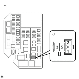
| *1 | No. 1 Engine Room Relay Block and No. 1 Junction Block Assembly |
| *2 | ST Relay Holder |
Remove the ST relay from the No. 1 engine room relay block and No. 1 junction block assembly.
Turn the ignition switch to ON.
Measure the voltage between ST relay terminal 1 and body ground.
- HINT:
- ·
Make a note of the measured voltage as it will be necessary for the inspecting the change in voltage in the next step. As the next step should be conducted under the same conditions, keep the ignition switch ON and do not install the ST relay.
·DTCs may be stored during this inspection. Check for DTCs and clear them using the GTS.
·If any voltage was measured with the ignition switch ON, one of the following malfunctions is suspected:
-Short to +B in the circuit of a connected ECU or park/neutral position switch assembly.
-Short to +B in the wire harness.
- Result:
Proceed to NEXT
NEXT
| *1 | No. 1 Engine Room Relay Block and No. 1 Junction Block Assembly |
| *2 | ST Relay Holder |
Disconnect the C62 park/neutral position switch assembly connector.
Measure the voltage between ST relay terminal 1 and body ground and compare it to the voltage measured in the previous step.
- Result:
Result Proceed to The voltage between ST relay terminal 1 and body ground does not change when the connector is disconnected. A The voltage between ST relay terminal 1 and body ground changes when the connector is disconnected. B
- HINT:
- ·
If the voltage is the same before and after disconnecting the connector, the park/neutral position switch assembly is normal.
·DTCs may be stored during this inspection. Check for DTCs and clear them using the GTS.
A
B
| *1 | No. 1 Engine Room Relay Block and No. 1 Junction Block Assembly |
| *2 | ST Relay Holder |
Disconnect the A46 ECM connector.
Measure the voltage between ST relay terminal 1 and body ground and compare it to the voltage measured in the previous step.
- Result:
Result Proceed to The voltage between ST relay terminal 1 and body ground does not change when the connector is disconnected. A The voltage between ST relay terminal 1 and body ground changes when the connector is disconnected. B
- HINT:
- ·
If the voltage is the same before and after disconnecting the connector, the ECM is normal.
·DTCs may be stored during this inspection. Check for DTCs and clear them using the GTS.
A
B
| *1 | No. 1 Engine Room Relay Block and No. 1 Junction Block Assembly |
| *2 | ST Relay Holder |
Disconnect the A124 engine stop and start ECU connector.
Measure the voltage between ST relay terminal 1 and body ground and compare it to the voltage measured in the previous step.
- Result:
Result Proceed to The voltage between ST relay terminal 1 and body ground does not change when the connector is disconnected. A The voltage between ST relay terminal 1 and body ground changes when the connector is disconnected. B
- HINT:
- ·
If the voltage is the same before and after disconnecting the connector, the engine stop and start ECU is normal.
·DTCs may be stored during this inspection. Check for DTCs and clear them using the GTS.
A
B
Disconnect the A46 ECM connector.
Disconnect the C62 park/neutral position switch assembly connector.
Disconnect the O62 certification ECU (smart key ECU assembly) connector.
Disconnect the A124 engine stop and start ECU connector.
Remove the ST relay from the No. 1 engine room relay block and No. 1 junction block assembly.
Measure the resistance according to the value(s) in the table below.
- Standard Resistance:
Tester Connection Condition Specified Condition A46-29 (STA), C62-9 (L), O62-1 (STA), A124-21 (STA) or 1 (ST relay) - Other terminals Always 10 kΩ or higher
- Result:
Proceed to OK NG
OK
NG
- Result:
Proceed to NEXT
NEXT