NETWORKING NETWORK GATEWAY ECU REMOVAL
CAUTION / NOTICE / HINT
The necessary procedures (adjustment, calibration, initialization or registration) that must be performed after parts are removed and installed, or replaced during central gateway ECU (network gateway ECU) removal/installation are shown below.
| Replaced Part or Performed Procedure | Necessary Procedures | Effect/Inoperative Function When Necessary Procedures are not Performed | Link |
|---|---|---|---|
| Central gateway ECU (network gateway ECU) | Update ECU security key | Vehicle Control History (RoB) are stored | ( 202304,999999,_V1,_143216,_0598316,RM100000002B3ML,) 202304,999999,_V1,_143216,_0598316,RM100000002B3ML,)
|
PROCEDURE

 55606
1.REMOVE NO. 1 INSTRUMENT PANEL UNDER COVER SUB-ASSEMBLY
55606
1.REMOVE NO. 1 INSTRUMENT PANEL UNDER COVER SUB-ASSEMBLY
55434F
2.REMOVE LOWER CENTER INSTRUMENT PANEL FINISH PANEL
55405B
3.REMOVE CENTER INSTRUMENT CLUSTER FINISH PANEL SUB-ASSEMBLY (except 10.25 Inch Display)
55405B
4.REMOVE CENTER INSTRUMENT CLUSTER FINISH PANEL SUB-ASSEMBLY (for 10.25 Inch Display)
55900
5.REMOVE AIR CONDITIONING CONTROL ASSEMBLY (for Electrical Control Type)
6.REMOVE LOWER CENTER INSTRUMENT CLUSTER FINISH PANEL SUB-ASSEMBLY (for Mechanical Control Type)
7.REMOVE CENTER INSTRUMENT PANEL SAFETY PAD RETAINER WITH HEATER CONTROL (for Mechanical Control Type)
67913
8.REMOVE FRONT DOOR SCUFF PLATE RH
- HINT:
-
Use the same procedure as for the LH side.
62111C
9.REMOVE COWL SIDE TRIM SUB-ASSEMBLY RH
- HINT:
-
Use the same procedure as for the LH side.
62311B
10.DISCONNECT FRONT DOOR OPENING TRIM WEATHERSTRIP RH
55318F
11.REMOVE NO. 2 INSTRUMENT SIDE PANEL
55670A
12.REMOVE CENTER INSTRUMENT PANEL REGISTER ASSEMBLY (for GTMC Made)
55470
13.REMOVE INSTRUMENT CLUSTER FINISH PANEL GARNISH ASSEMBLY
55670A
14.REMOVE CENTER INSTRUMENT PANEL REGISTER ASSEMBLY (for TFTM Made)
55607
15.REMOVE NO. 2 INSTRUMENT PANEL UNDER COVER SUB-ASSEMBLY
55550
16.REMOVE GLOVE COMPARTMENT DOOR ASSEMBLY
55433B
17.REMOVE LOWER NO. 2 INSTRUMENT PANEL FINISH PANEL
82877
18.REMOVE ECU INTEGRATION BOX RH
for NR Series Engine:
Disconnect each connector.

Disengage the 2 clamps.
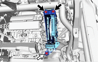

|
Nut |

|
Bolt |
Remove the 2 nuts, bolt and ECU integration box RH.
except NR Series Engine:
Disconnect each connector.
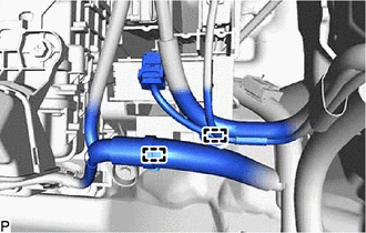
Disengage the 2 clamps.
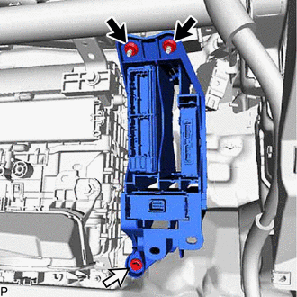
|
|
Nut |
|
|
Bolt |
Remove the 2 nuts, bolt and ECU integration box RH.
89111
19.REMOVE CENTRAL GATEWAY ECU (NETWORK GATEWAY ECU)
for NR Series Engine:
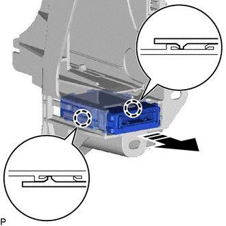

|
Remove in this Direction |
Disengage the 2 claws to remove the central gateway ECU (network gateway ECU) as shown in the illustration.
- NOTICE:
- ·
If the ECU integration box RH is deformed or damaged, replace it.
·Do not bend the 2 claws more than necessary.
except NR Series Engine:
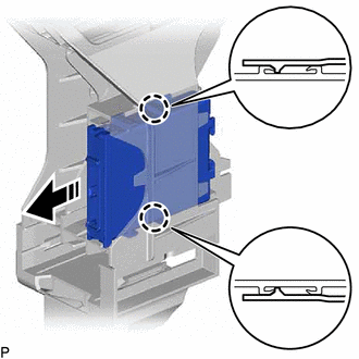
|
|
Remove in this Direction |
Disengage the 2 claws to remove the central gateway ECU (network gateway ECU) as shown in the illustration.
- NOTICE:
- ·
If the ECU integration box RH is deformed or damaged, replace it.
·Do not bend the 2 claws more than necessary.