INTERIOR PANELS / TRIM FRONT CONSOLE BOX REMOVAL
PROCEDURE

 55606
1.REMOVE NO. 1 INSTRUMENT PANEL UNDER COVER SUB-ASSEMBLY
55606
1.REMOVE NO. 1 INSTRUMENT PANEL UNDER COVER SUB-ASSEMBLY
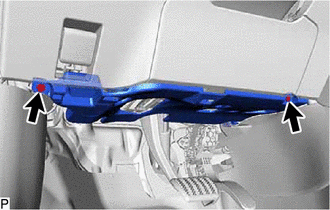
Remove the 2 screws.
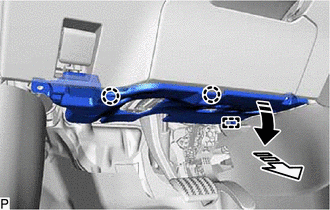

|
Remove in this Direction (1) |

|
Remove in this Direction (2) |
Pull the No. 1 instrument panel under cover sub-assembly in the direction indicated by the arrow (1) shown in the illustration to disengage the 2 claws.
Pull the No. 1 instrument panel under cover sub-assembly in the direction indicated by the arrow (2) shown in the illustration to disengage the guide.
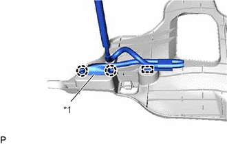
| *1 | DLC3 |
Disengage the 2 claws to disconnect the DLC3.
Disengage the clamp to remove the No. 1 instrument panel under cover sub-assembly.
w/ Illumination:
Disconnect the connector.
58816D
2.REMOVE FRONT NO. 1 CONSOLE BOX INSERT
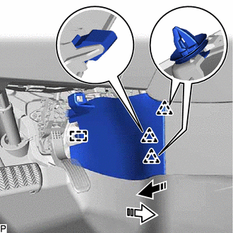
|
|
Remove in this Direction (1) |
|
|
Remove in this Direction (2) |
Pull the front No. 1 console box insert in the direction indicated by the arrow (1) shown in the illustration to disengage the 3 clips.
Pull the front No. 1 console box insert in the direction indicated by the arrow (2) shown in the illustration to disengage the guide and remove it.
55434F
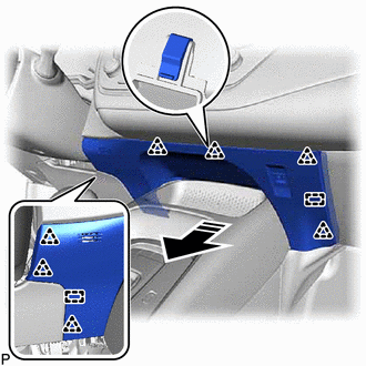
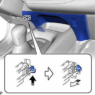
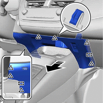
3.REMOVE LOWER CENTER INSTRUMENT PANEL FINISH PANEL
for Type A:
|
|
Remove in this Direction |
Disengage the 7 clips and each guide as shown in the illustration.
|
|
Remove in this Direction (1) |
|
|
Remove in this Direction (2) |
Disengage the hook as shown in the illustration.
Disconnect each connector to remove the lower center instrument panel finish panel.
for Type B:
|
|
Remove in this Direction |
Disengage the 7 clips and each guide as shown in the illustration.
Disengage the clamp and disconnect each connector to remove the lower center instrument panel finish panel.
58817A
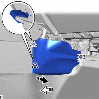
4.REMOVE FRONT NO. 2 CONSOLE BOX INSERT
|
|
Remove in this Direction (1) |
|
|
Remove in this Direction (2) |
Pull the front No. 2 console box insert in the direction indicated by the arrow (1) shown in the illustration to disengage the 2 clips.
Pull the front No. 2 console box insert in the direction indicated by the arrow (2) shown in the illustration to disengage the guide and remove it.
58831A
5.REMOVE FRONT CONSOLE UPPER PANEL GARNISH
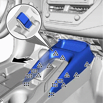
|
|
Remove in this Direction |
Disengage the 9 clips and 6 guides as shown in the illustration.
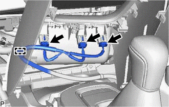
Disconnect each connector.
Disengage the clamp to remove the front console upper panel garnish.
33504F
6.REMOVE SHIFT LEVER KNOB SUB-ASSEMBLY (for CVT)
for K313:
for K320 / K321:
for K120 / K121:
33504F
7.REMOVE SHIFT LEVER KNOB SUB-ASSEMBLY (for HV Model)
35970F
8.REMOVE POSITION INDICATOR HOUSING ASSEMBLY
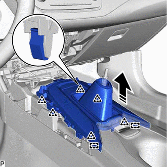
|
|
Remove in this Direction |
Disengage the 6 clips and 2 guides as shown in the illustration.
Disconnect each connector to remove the position indicator housing assembly.
9.REMOVE CONSOLE CUP HOLDER BOX SUB-ASSEMBLY
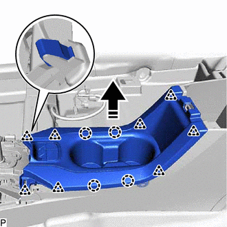
|
|
Remove in this Direction |
Disengage the 4 claws and 8 clips as shown in the illustration.
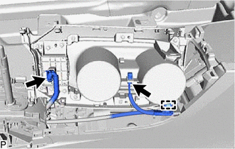
Disconnect the 2 connectors.
Disengage the clamp to remove the console cup holder box sub-assembly.
10.REMOVE CONSOLE REAR END PANEL SUB-ASSEMBLY

|
Protective Tape |
|
|
Remove in this Direction |
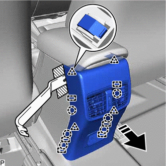
Apply protective tape to the area shown in the illustration.
Using a moulding remover, disengage the 6 claws, 4 clips and 6 guides as shown in the illustration to remove the console rear end panel sub-assembly.
w/ USB Charger:
Disconnect the connector.
58815C
11.REMOVE CONSOLE BOX CARPET
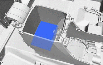
Remove the console box carpet.
12.REMOVE BLE INDOOR DIGITAL KEY RECEIVER ASSEMBLY (w/ Digital Key System)
13.REMOVE CONSOLE BOX ASSEMBLY
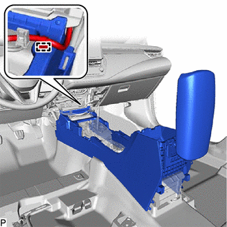
Disengage the clamp.
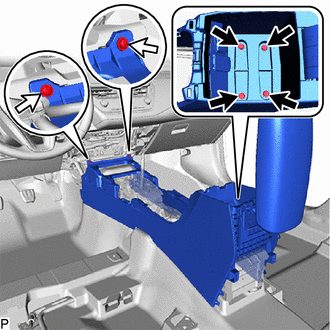

|
Bolt |

|
Screw |
Remove the 4 bolts and 2 screws.
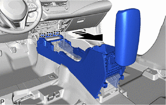
|
|
Remove in this Direction |
Disengage the 3 guides as shown in the illustration to remove the console box assembly.
55620F
14.REMOVE CONSOLE BOX CUP HOLDER ASSEMBLY
- HINT:
-
Perform this procedure only when replacement of the console box cup holder assembly.
w/ Illumination:
Remove the instrument panel under tray wall retainer.
Remove the electric parking brake switch assembly.
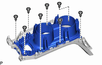
Remove the 8 screws and remove the console box cup holder assembly.