HEATING / AIR CONDITIONING AIR CONDITIONING SYSTEM(for Gasoline Model (NR Series) with Manual Air Conditioning System for Electrical Control Type) TERMINALS OF ECU
CHECK AIR CONDITIONING AMPLIFIER ASSEMBLY
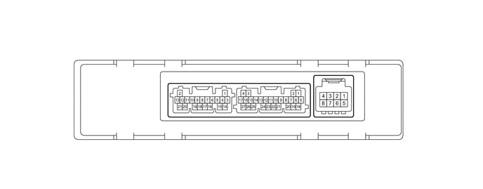
| *A | w/o Rear Air Duct | *B | w/ Rear Air Duct |
- HINT:
-
Check from the rear of the connector while it is connected to the air conditioning amplifier assembly.
| Terminal No.
(Symbol) |
Wiring Color | Terminal Description | Condition | Specified Condition |
|---|---|---|---|---|
| I48-1 (TAM) - I48-14 (SG-2) | R - BR | Thermistor assembly signal | ·
Ignition switch ON ·
Ambient temperature: 25°C (77°F) |
1.05 to 1.45 V |
·
Ignition switch ON ·
Ambient temperature: 40°C (104°F) |
0.64 to 0.87 V | |||
| I48-6 (PRE) - I48-15 (SG-4) | L - G | Air conditioner pressure sensor signal | ·
Ignition switch ON ·
Air conditioning system operating ·
Refrigerant pressure: Abnormal pressure (more than 3.025 MPaG (30.8 kgf/cm2, 439 psi) |
4.73 V or higher |
·
Ignition switch ON ·
Air conditioning system operating ·
Refrigerant pressure: Abnormal pressure (less than 0.176 MPaG (1.8 kgf/cm2, 26 psi)) |
Below 0.62 V | |||
·
Ignition switch ON ·
Air conditioning system operating ·
Refrigerant pressure: Normal pressure (less than 3.025 MPaG (30.8 kgf/cm2, 439 psi) and more than 0.176 MPaG (1.8 kgf/cm2, 26 psi)) |
0.62 to 4.73 V*3 | |||
| I48-11 (S5-3) - I48-15 (SG-4) | B - G | Power supply for air conditioner pressure sensor | Ignition switch ON | 4.75 to 5.25 V |
| Ignition switch off | Below 1 V | |||
| I48-14 (SG-2) - Body ground | BR - Body ground | Ground for thermistor assembly | Always | Below 1 V |
| I48-15 (SG-4) - Body ground | G - Body ground | Ground for air conditioner pressure sensor | Always | Below 1 V |
| I49-1 (CANL) - I49-2 (CANH) | W - G | CAN communication system | CAN communication is performed | Pulse generation |
| I49-5 (B) - I49-17 (GND) | LG - W-B | Power source (Back-up) | Always | 11 to 14 V |
| I49-6 (IG+) - I49-17 (GND) | SB - W-B | Power source (IG) | Ignition switch ON | 11 to 14 V |
| Ignition switch off | Below 1 V | |||
| I49-7 (LIN1) - I49-17 (GND) | V - W-B | LIN communication signal | Ignition switch ON | Pulse generation
(See waveform 2) |
| I49-17 (GND) - Body ground | W-B - Body ground | Ground for main power supply | Always | Below 1 V |
| I49-18 (SOL+) - I49-17 (GND) | B - W-B | Compressor solenoid operation signal | ·
Engine running ·
Blower switch: LO ·
A/C switch: On |
Pulse generation
(See waveform 4) |
| I49-21 (BLW) - I49-17 (GND) | W - W-B | Blower motor speed control signal | ·
Ignition switch ON ·
Blower switch: LO |
Pulse generation
(See waveform 1) |
| m3-2 (BUSG) - Body ground*1 | B - | Ground for BUS IC | Always | Below 1 V |
| m3-3 (BUS) - m3-2 (BUSG)*1 | L - B | BUS IC control signal | Ignition switch ON | Pulse generation
(See waveform 3) |
| m3-4 (BUSB) - m3-2 (BUSG)*1 | R - B | Power supply for BUS IC | Always | 11 to 14 V |
| m3-5 (SG-3) - Body ground*1 | GR - Body ground | Ground for No. 1 cooler thermistor | Always | Below 1 V |
| m3-6 (TE) - m3-5 (SG-3)*1 | GR - GR | No. 1 cooler thermistor signal | ·
Ignition switch ON ·
Evaporator temperature: 0°C (32°F) |
1.7 to 2.1 V |
·
Ignition switch ON ·
Evaporator temperature: 15°C (59°F) |
0.9 to 1.3 V | |||
| z1-2 (BUSG) - Body ground*2 | - | Ground for BUS IC | Always | Below 1 V |
| z1-3 (BUS) - z1-2 (BUSG)*2 | - | BUS IC control signal | Ignition switch ON | Pulse generation
(See waveform 3) |
| z1-4 (BUSB) - z1-2 (BUSG)*2 | - | Power supply for BUS IC | Always | 11 to 14 V |
| z1-5 (SG-3) - Body ground*2 | - | Ground for No. 1 cooler thermistor | Always | Below 1 V |
| z1-6 (TE) - z1-5 (SG-3)*2 | - | No. 1 cooler thermistor signal | ·
Ignition switch ON. ·
Evaporator temperature: 0°C (32°F) |
1.7 to 2.1 V |
·
Ignition switch ON ·
Evaporator temperature: 15°C (59°F) |
0.9 to 1.3 V |
*1: w/o Rear Air Duct
*2: w/ Rear Air Duct
*3: While sensor voltage is 5 V.
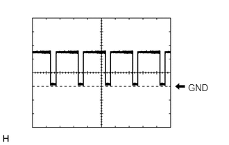
Waveform 1:
| Item | Content |
|---|---|
| Terminal No. | I49-21 (BLW) - I49-17 (GND) |
| Tool Setting | 2 V/DIV., 1 ms./DIV. |
| Condition | ·
Ignition switch ON ·
Blower switch: LO |
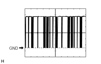
Waveform 2:
| Item | Content |
|---|---|
| Terminal No. | I49-7 (LIN1) - I49-17 (GND) |
| Tool Setting | 2 V/DIV., 20 ms./DIV. |
| Condition | Ignition switch ON |
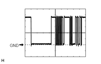
Waveform 3:
| Item | Content |
|---|---|
| Terminal No. | m3-3 (BUS) - m3-2 (BUSG)*1
z1-3 (BUS) - z1-2 (BUSG)*2 |
| Tool Setting | 2 V/DIV., 2 ms./DIV. |
| Condition | Ignition switch ON |
*1: w/o Rear Air Duct
*2: w/ Rear Air Duct
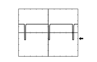
Waveform 4:
| Item | Content |
|---|---|
| Terminal No. | I49-18 (SOL+) - I49-17 (GND) |
| Tool Setting | 5 V/DIV., 500 μs./DIV. |
| Condition | ·
Engine running ·
Blower switch: LO ·
A/C switch: On |
CHECK AIR CONDITIONING CONTROL ASSEMBLY

- HINT:
-
Check from the rear of the connector while it is connected to the air conditioning control assembly.
| Terminal No.
(Symbol) |
Wiring Color | Terminal Description | Condition | Specified Condition |
|---|---|---|---|---|
| I37-7 (LIN1) - Body ground | V - Body ground | LIN communication signal | Ignition switch ON | Pulse generation
(See waveform) |
| I37-8 (ILL+) - Body ground | P - Body ground | Illumination signal | Taillight off | Below 1 V |
| Taillight on | 11 to 14 V | |||
| I37-9 (IG+) - I37-13 (GND) | G - W-B | Power source (IG) | Ignition switch off | Below 1 V |
| Ignition switch ON | 11 to 14 V | |||
| I37-13 (GND) - Body ground | W-B - Body ground | Ground for air conditioning control assembly | Always | Below 1 V |
| I37-14 (ILL-) - Body ground | W - Body ground | Illumination signal | Always | Below 1 V |
Waveform:
| Item | Content |
|---|---|
| Terminal No. | I37-7 (LIN1) - Body ground |
| Tool Setting | 2 V/DIV., 20 ms./DIV. |
| Condition | Ignition switch ON |