THEFT DETERRENT / KEYLESS ENTRY SMART ENTRY AND START SYSTEM(for Start Function, Gasoline Model (NR Series)) B2782 Power Source Control ECU Malfunction
DESCRIPTION
The certification ECU (smart key ECU assembly) has a power source mode switching function.
This DTC is stored when the IGE input (the steering lock motor activation permission signal) sent directly from the certification ECU (smart key ECU assembly) to the steering lock ECU (steering lock actuator or upper bracket assembly) is determined to be abnormal.
- HINT:
-
The steering lock ECU (steering lock actuator or upper bracket assembly) is not connected to the CAN communication system. However, the steering lock ECU (steering lock actuator or upper bracket assembly) is connected to the certification ECU (smart key ECU assembly) via LIN communication and communicates with other components via CAN communication through the certification ECU (smart key ECU assembly).
| DTC No. | Detection Item | DTC Detection Condition | Trouble Area | Note |
|---|---|---|---|---|
| B2782 | Power Source Control ECU Malfunction | Either of the following conditions is met (1-trip detection logic (Only output while a malfunction is present and the engine switch is on (IG).)):
·
The steering lock motor activation command circuit has a short circuit. ·
The steering lock motor activation command circuit has an open circuit.
|
·
Steering lock ECU (steering lock actuator or upper bracket assembly) ·
Certification ECU (smart key ECU assembly) ·
Wire harness or connector |
DTC Output Confirmation Operation: Perform a steering lock/unlock operation. (The steering locks when a door is opened with the shift lever in P and the engine switch off. The steering unlocks when the engine switch is turned on (ACC) or on (IG) while carrying the key.) |
| Vehicle Condition when Malfunction Detected | Fail-safe Function when Malfunction Detected |
|---|---|
| The steering cannot be locked or unlocked. For this reason, the engine cannot be started. | Prohibits the engine from being started (the engine does not crank). |
| DTC No. | Data List and Active Test |
|---|---|
| B2782 | - |
WIRING DIAGRAM
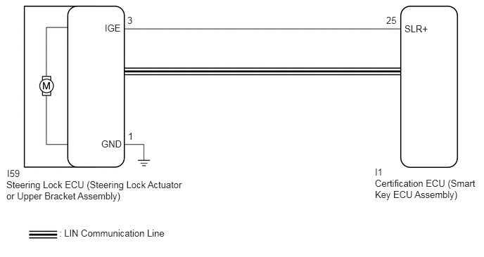
CAUTION / NOTICE / HINT
- NOTICE:
- ·
When using the GTS with the engine switch off, connect the GTS to the DLC3 and turn a courtesy light switch on and off at intervals of 1.5 seconds or less until communication between the GTS and the vehicle begins. Then select Model Code "KEY REGIST" under manual mode and enter the following menus: Body Electrical / Entry&Start(CAN). While using the GTS, periodically turn a courtesy light switch on and off at intervals of 1.5 seconds or less to maintain communication between the GTS and the vehicle.
·The smart entry and start system (for Start Function) uses the LIN communication system and CAN communication system. Inspect the communication function by following How to Proceed with Troubleshooting. Troubleshoot the smart entry and start system (for Start Function) after confirming that the communication systems are functioning properly.
·When disconnecting the cable from the negative (-) battery terminal, some systems need to be initialized after the cable is reconnected.
·Before replacing the steering lock ECU (steering lock actuator or upper bracket assembly) or certification ECU (smart key ECU assembly), refer to Service Bulletin.
PROCEDURE
Disconnect the I59 steering lock ECU (steering lock actuator or upper bracket assembly) connector.
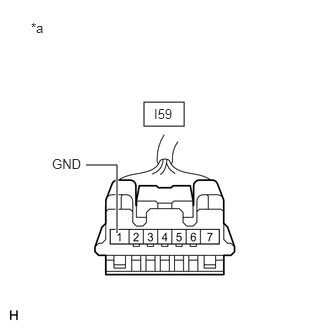
| *a | Front view of wire harness connector
(to Steering Lock ECU (Steering Lock Actuator or Upper Bracket Assembly)) |
Measure the resistance according to the value(s) in the table below.
- Standard Resistance:
Tester Connection Condition Specified Condition I59-1 (GND) - Body ground Always Below 1 Ω
- Result:
Proceed to OK NG
OK
NG
Connect the I59 steering lock ECU (steering lock actuator or upper bracket assembly) connector.
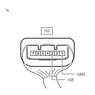
| *a | Component with harness connected
(Steering Lock ECU (Steering Lock Actuator or Upper Bracket Assembly)) |
Measure the voltage according to the value(s) in the table below.
- Standard Voltage:
Tester Connection Condition Specified Condition I59-3 (IGE) - I59-1 (GND) Steering lock motor operating when all conditions met, and then door opened:
The steering is unlocked.
The engine switch is off.
The shift lever is in P.
11 to 14 V → Below 1 V
- Result:
Proceed to OK NG
OK
NG
Clear the DTCs.
- Body Electrical > Entry&Start > Clear DTCs
- 50002 125
Disconnect the cable from the negative (-) battery terminal, wait for 30 seconds or more, and then reconnect the cable to the negative (-) battery terminal to clear the record of malfunctions stored in the Data List.
- CAUTION:
-
After turning the engine switch off, waiting time may be required before disconnecting the cable from the battery terminal. Therefore, make sure to read the disconnecting the cable from the battery terminal notices before proceeding with work.
- Result:
Proceed to NEXT
NEXT
Perform the DTC output confirmation operation.
Check if DTC B2782 is output.
- Body Electrical > Entry&Start > Trouble Codes
- 50001 125
- Result:
Result Proceed to DTC B2782 is not output A DTC B2782 is output B
A
B
Disconnect the I59 steering lock ECU (steering lock actuator or upper bracket assembly) connector.
Disconnect the I1 certification ECU (smart key ECU assembly) connector.
Check for deformation and corrosion of the connector case and terminals.
- OK:
There is no deformation or corrosion of the connector case or terminals.
Measure the resistance according to the value(s) in the table below.
- Standard Resistance:
Tester Connection Condition Specified Condition I59-3 (IGE) - I1-25 (SLR+) Always Below 1 Ω I59-3 (IGE) or I1-25 (SLR+) - Other terminals and body ground Always 10 kΩ or higher
- Result:
Proceed to OK NG
OK
NG