RM3660EC _58 Vehicle Interior _080744 INTERIOR PANELS / TRIM _0394267 ROOF HEADLINING A

INTERIOR PANELS / TRIM  ROOF HEADLINING  REASSEMBLY  


PROCEDURE

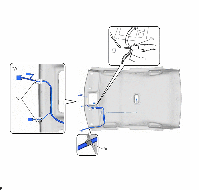
Hide 82171 1.INSTALL NO. 1 ROOF WIRE (for Normal Roof)

a.

Align the marking tape (A) on the No. 1 roof wire with the vehicle front side tab of the roof headlining assembly.
B674942C01
3.708,5.375 3.25,5.177 true 4.719,1.958 5.073,2.094 false 4.719,1.677 5.396,1.427 true 1.271,2.927 0.771,3.563 0.771,3.563 1.281,4.313 false 0.448,2.375 0.698,2.542 0.25,0.167 12 false *A 3.729,5.281 3.948,5.49 0.219,0.208 10 false *a 5.115,2.031 5.333,2.24 0.219,0.208 10 false *c 5.406,1.313 5.625,1.521 0.219,0.208 10 false *b 0.573,3.458 0.792,3.667 0.219,0.208 10 false *d
*A for Front Side with Connector - -
*a Marking Tape (A) *b Portion (A)
*c Marking *d Notch


b.

Align the portion (A) with the markings on the roof headlining assembly.


c.

for Front Side with Connector:

i.

Connect the No. 1 roof wire to each notch.


d.

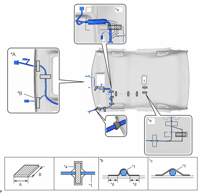
for Type A:

i.

Install the No. 1 roof wire to the roof headlining assembly with adhesive tape.
B674943C01
0.167,5.583 7,6.75 6.833,1.167 6.167,6.104 6.469,5.917 true 4.427,6.083 4.667,5.927 true 3.24,6.188 3.24,6.49 true 2.667,5.917 2.417,5.917 true 1.917,5.583 1.917,6.75 false 3.5,5.583 3.5,6.75 false 5.25,5.583 5.25,6.75 false 0.854,3.333 1.333,3.521 true 0.677,6.469 0.927,6.698 0.25,0.229 10 false A 1.375,6.115 1.625,6.344 0.25,0.229 10 false B 3.531,5.615 3.781,5.844 0.25,0.229 10 false *b 5.292,5.625 5.542,5.854 0.25,0.229 10 false *c 3.917,6.458 4.167,6.688 0.25,0.229 10 false *d 4.708,6.458 4.958,6.688 0.25,0.229 10 false *d 6.469,5.813 6.719,6.042 0.25,0.229 10 false *1 3.146,6.5 3.365,6.656 0.219,0.156 10 false *1 4.677,5.833 4.896,5.99 0.219,0.156 10 false *1 2.26,5.833 2.479,5.99 0.219,0.156 10 false *a 5.25,4.198 5.49,4.406 0.24,0.208 10 true *e 4.094,0.26 4.344,0.427 0.25,0.167 10 true *e 0.375,1.823 0.708,2.146 0.333,0.323 12 false *A 0.615,3.208 0.948,3.531 0.333,0.323 12 false *B
*A for Front Side with Connector *B w/ ETC
*1 No. 1 Roof Wire - -
*a Marking *b Correct
*c Incorrect *d 10 mm (0.394 in.) or more
*e Adjustment Area - -
V100155

Adhesive Tape - -


Adhesive Tape Size
Area Dimension Area Dimension
A 20 mm (0.787 in.) B 80 mm (3.15 in.) or more

NOTICE:
·

Apply the tape securely in place.

·

Do not touch the adhesive surface when applying the tape to prevent adhesion failure.


HINT:

Secure the extra length of the No. 1 roof wire in the adjustment area.


e.

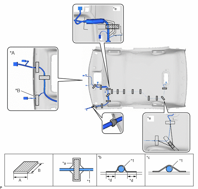
for Type B:

i.

Install the No. 1 roof wire to the roof headlining assembly with adhesive tape.
B674944C01
0.167,5.583 7,6.75 6.833,1.167 6.156,6.115 6.438,5.833 true 4.427,6.104 4.708,5.823 true 3.24,6.177 3.24,6.479 true 2.667,5.917 2.417,5.917 true 1.917,5.583 1.917,6.75 false 3.5,5.583 3.5,6.75 false 5.25,5.583 5.25,6.75 false 0.76,3.292 1.323,3.521 true 0.677,6.448 0.927,6.677 0.25,0.229 10 false A 1.375,6.094 1.625,6.323 0.25,0.229 10 false B 3.542,5.615 3.792,5.844 0.25,0.229 10 false *b 5.302,5.625 5.552,5.854 0.25,0.229 10 false *c 3.917,6.448 4.167,6.677 0.25,0.229 10 false *d 4.688,6.458 4.938,6.688 0.25,0.229 10 false *d 6.49,5.74 6.74,5.969 0.25,0.229 10 false *1 3.146,6.49 3.365,6.646 0.219,0.156 10 false *1 4.729,5.74 4.948,5.896 0.219,0.156 10 false *1 2.26,5.833 2.479,5.99 0.219,0.156 10 false *a 5.333,4.198 5.573,4.406 0.24,0.208 10 true *e 4.094,0.229 4.344,0.396 0.25,0.167 10 true *e 0.354,1.813 0.688,2.135 0.333,0.323 12 false *A 0.552,3.177 0.885,3.5 0.333,0.323 12 false *B
*A for Front Side with Connector *B w/ ETC
*1 No. 1 Roof Wire - -
*a Marking *b Correct
*c Incorrect *d 10 mm (0.394 in.) or more
*e Adjustment Area - -
V100155

Adhesive Tape - -


Adhesive Tape Size
Area Dimension Area Dimension
A 20 mm (0.787 in.) B 80 mm (3.15 in.) or more

NOTICE:
·

Apply the tape securely in place.

·

Do not touch the adhesive surface when applying the tape to prevent adhesion failure.


HINT:

Secure the extra length of the No. 1 roof wire in the adjustment area.


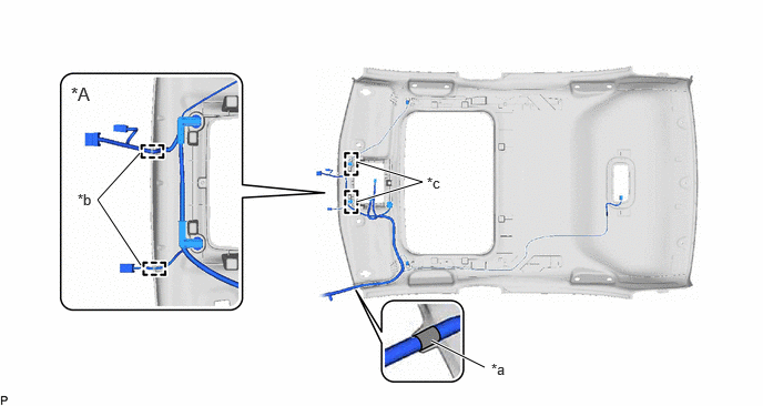
Hide 82171 2.INSTALL NO. 1 ROOF WIRE (for Moon Roof)

a.

Align the marking tape (A) on the No. 1 roof wire with the vehicle front side tab of the roof headlining assembly.
B674945C01
4.052,3.198 4.552,3.448 true 1.313,1.438 0.917,1.875 0.917,1.875 1.323,2.49 true 3.354,1.521 3.969,1.708 3.969,1.708 3.344,1.896 true 4.615,3.385 4.99,3.625 0.375,0.24 10 false *a 0.729,1.792 0.938,1.958 0.208,0.167 10 false *b 4.01,1.635 4.219,1.802 0.208,0.167 10 false *c 0.667,0.781 1.042,1.021 0.375,0.24 12 false *A
*A for Front Side with Connector - -
*a Marking Tape (A) *b Notch
*c Clamp - -


b.

Engage each clamp.


c.

for Front Side with Connector:

i.

Connect the No. 1 roof wire to each notch.


d.

Install the No. 1 roof wire to the roof headlining assembly with adhesive tape.
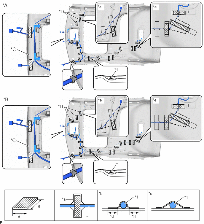
B674946C01
0.167,6.667 7,7.75 6.833,1.083 1.917,7.75 1.917,6.667 false 3.417,7.75 3.417,6.667 false 5.167,7.75 5.167,6.667 false 2.323,7.01 2.573,7.01 false 3.125,7.24 3.125,7.49 true 4.708,6.906 4.375,7.156 true 6.438,6.927 6.104,7.177 true 4.083,5.781 3.917,6.01 true 4.073,2.49 3.906,2.719 true 2.781,0.5 2.25,0.417 2.25,0.417 2.802,0.688 true 2.677,0.813 2.25,0.417 true 2.792,3.927 2.25,3.75 2.25,3.75 2.677,4.083 true 2.448,4.177 2.25,3.75 true 1.052,1.938 0.604,1.74 true 1.021,5.135 0.573,4.938 true 0.625,7.531 0.875,7.698 0.25,0.167 10 false A 2.177,6.906 2.396,7.115 0.219,0.208 10 false *a 3.031,7.531 3.281,7.656 0.25,0.125 10 false *1 4.74,6.833 4.99,6.958 0.25,0.125 10 false *1 6.479,6.854 6.729,6.979 0.25,0.125 10 false *1 3.865,7.51 4.083,7.677 0.219,0.167 10 false *d 4.635,7.521 4.885,7.688 0.25,0.167 10 false *d 3.469,6.708 3.688,6.917 0.219,0.208 10 false *b 5.219,6.708 5.438,6.917 0.219,0.208 10 false *c 5.365,3.427 5.583,3.635 0.219,0.208 10 true *e 4.052,5.677 4.302,5.802 0.25,0.125 10 false *1 5.375,0.156 5.594,0.365 0.219,0.208 10 true *e 1.323,7.167 1.573,7.333 0.25,0.167 10 false B 4.021,2.365 4.271,2.49 0.25,0.125 10 false *1 0.083,0.083 0.417,0.344 0.333,0.26 12 false *A 0.115,3.385 0.417,3.604 0.302,0.219 12 false *B 0.365,4.823 0.698,5.083 0.333,0.26 12 false *C 3.438,0.156 3.656,0.365 0.219,0.208 10 true *e 3.448,3.427 3.667,3.635 0.219,0.208 10 true *e 2.031,3.635 2.313,3.896 0.281,0.26 12 false *D 2.063,0.302 2.344,0.563 0.281,0.26 12 false *D 0.375,1.625 0.708,1.885 0.333,0.26 12 false *C
*A for Type A *B for Type B
*C w/ ETC *D w/ Navigation System
*1 No. 1 Roof Wire - -
*a Marking *b Correct
*c Incorrect *d 10 mm (0.394 in.) or more
*e Adjustment Area - -
V100155

Adhesive Tape - -


Adhesive Tape Size
Area Dimension Area Dimension
A 20 mm (0.787 in.) B 80 mm (3.15 in.) or more

NOTICE:
·

Apply the tape securely in place.

·

Do not touch the adhesive surface when applying the tape to prevent adhesion failure.


HINT:

Secure the extra length of the No. 1 roof wire in the adjustment area.


Hide 63342 4.INSTALL NO. 2 ROOF SILENCER PAD (for Normal Roof)

a.

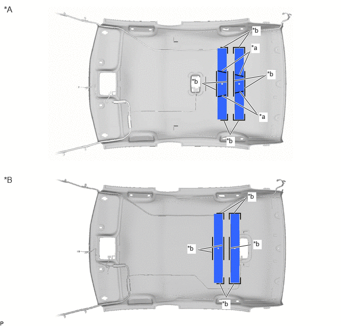
Align the 2 No. 2 roof silencer pads with the markings on the roof headlining assembly and install it using hot-melt glue as shown in the illustration.
B610742C01
4.833,2.833 4.708,2.542 true 4.833,2.833 5.01,2.542 true 4.25,1.75 4.771,1.719 true 5.021,0.99 5.25,0.667 true 4.25,1.75 4.531,1.885 true 4.917,1.698 5.583,1.583 true 5.146,1.854 5.583,1.583 true 4.667,1.49 5.25,1.083 true 5.031,1.583 5.25,1.083 true 5.417,2.417 5.042,1.927 true 5.417,2.417 4.667,2.01 true 4.677,1 5.25,0.667 true 4.833,5.219 5.271,5.146 true 4.667,4.479 5.167,4.167 true 4.917,4.479 5.167,4.167 true 4.167,5.25 4.667,5.156 true 4.167,5.25 4.448,5.302 true 4.615,5.958 4.75,6.25 true 4.917,5.969 4.75,6.25 true 0.083,0.094 0.458,0.333 0.375,0.24 12 false *A 0.083,3.677 0.458,3.917 0.375,0.24 12 false *B 5.281,0.917 5.458,1.115 0.177,0.198 10 true *a 5.448,2.365 5.625,2.563 0.177,0.198 10 true *a 5.302,0.552 5.479,0.75 0.177,0.198 10 true *b 5.615,1.469 5.792,1.667 0.177,0.198 10 true *b 4.031,1.625 4.208,1.823 0.177,0.198 10 true *b 4.76,2.875 4.938,3.073 0.177,0.198 10 true *b 4.667,6.302 4.844,6.5 0.177,0.198 10 true *b 5.208,4.042 5.385,4.24 0.177,0.198 10 true *b 3.938,5.135 4.115,5.333 0.177,0.198 10 true *b 5.323,5.042 5.5,5.24 0.177,0.198 10 true *b
*A for Type A *B for Type B
*a Hot-melt Glue *b Marking


Hide 63341 5.INSTALL NO. 1 ROOF SILENCER PAD (for Normal Roof)

a.

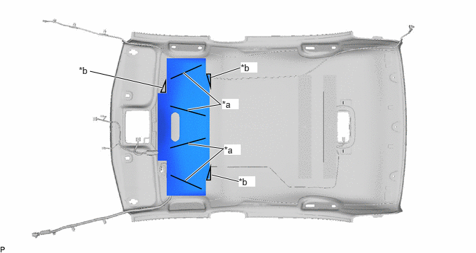
Align the No. 1 roof silencer pad with the markings on the roof headlining assembly and install it using hot-melt glue as shown in the illustration.
B674947C01
2.823,1.656 3.323,1.573 3.323,1.573 2.76,1.094 true 2.792,2.719 3.365,2.24 3.365,2.24 2.833,2.167 true 1.354,1.073 2.448,1.323 true 3.177,1.167 3.615,1.021 true 3.188,2.635 3.615,2.74 true 1.188,0.979 1.438,1.135 0.25,0.156 10 false *b 3.344,1.49 3.594,1.646 0.25,0.156 10 true *a 3.375,2.177 3.625,2.333 0.25,0.156 10 true *a 3.625,0.938 3.875,1.094 0.25,0.156 10 true *b 3.594,2.656 3.844,2.813 0.25,0.156 10 true *b
*a Hot-melt Glue *b Marking


Hide 86255F 6.INSTALL MICROPHONE CASE (for 10.25 Inch Display)

HINT:

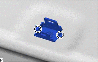
Use the same procedure for all microphone cases.

a.
B647800

Engage the 2 claws to install the microphone case.


Hide F1969B 8.INSTALL TOLL COLLECTION ECU SEAL TAPE (w/ ETC for Type A)