RM3660EC
_58
Vehicle Interior
_080793
METER / GAUGE / DISPLAY
_0473831
TRIP SWITCH
A
METER / GAUGE / DISPLAY TRIP SWITCH INSTALLATION
PROCEDURE

 84975
1.INSTALL TRIP SWITCH
84975
1.INSTALL TRIP SWITCH
a.
0,0 0,0
false

|
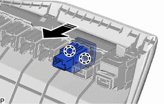
Install in this Direction |
Engage the 2 claws to install the trip switch as shown in the illustration.
55432B
2.INSTALL LOWER INSTRUMENT PANEL FINISH PANEL
53601
3.CONNECT HOOD LOCK CONTROL LEVER SUB-ASSEMBLY
55606
4.INSTALL NO. 1 INSTRUMENT PANEL UNDER COVER SUB-ASSEMBLY
55317E
5.INSTALL NO. 1 INSTRUMENT SIDE PANEL