DOOR / HATCH REAR DOOR ADJUSTMENT
CAUTION / NOTICE / HINT
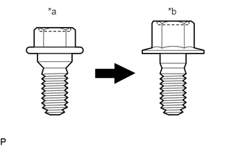
| *a | Centering Bolt |
| *b | Standard Bolt |
- HINT:
- ·
Use the same procedure for the RH side and LH side.
·The following procedure is for the LH side.
·Centering bolts are used to install the door hinges to the vehicle body and door. The door cannot be adjusted with the centering bolts installed. Substitute the centering bolts with standard bolts when making adjustments.
·The specified torque for standard bolts is shown in the standard bolt chart.
PROCEDURE

 1.INSPECT REAR DOOR (except ALLION)
Check that the clearance measurements of areas a through o are within each standard range.
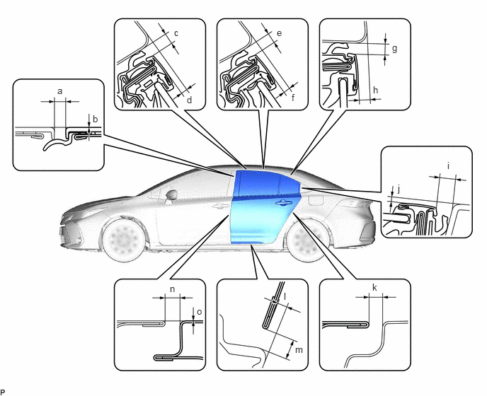
| Area | Measurement | Area | Measurement |
|---|---|---|---|
| a | 2.5 to 6.5 mm (0.0984 to 0.256 in.) | b | -2.0 to 2.0 mm (-0.0787 to 0.0787 in.) |
| c | 3.15 to 6.55 mm (0.124 to 0.258 in.) | d | 1.55 to 5.55 mm (0.0610 to 0.219 in.) |
| e | 3.25 to 6.65 mm (0.128 to 0.262 in.) | f | 1.55 to 5.55 mm (0.0610 to 0.219 in.) |
| g | 3.15 to 6.55 mm (0.124 to 0.258 in.) | h | 2.65 to 6.65 mm (0.104 to 0.262 in.) |
| i | 5.2 to 8.6 mm (0.205 to 0.339 in.) | j | -0.3 to 3.7 mm (-0.0118 to 0.146 in.) |
| k | 2.5 to 5.5 mm (0.0984 to 0.217 in.) | l | -0.15 to 4.85 mm (-0.00591 to 0.191 in.) |
| m | 3.15 to 8.15 mm (0.124 to 0.321 in.) | n | 2.8 to 5.2 mm (0.1102 to 0.2047 in.) |
| o | -1.2 to 1.2 mm (-0.0472 to 0.0472 in.) | - | - |
2.INSPECT REAR DOOR (for ALLION)
Check that the clearance measurements of areas a through o are within each standard range.
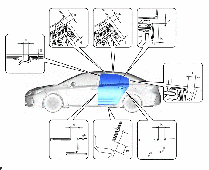
| Area | Measurement | Area | Measurement |
|---|---|---|---|
| a | 2.5 to 6.5 mm (0.0984 to 0.256 in.) | b | -2.0 to 2.0 mm (-0.0787 to 0.0787 in.) |
| c | 3.15 to 6.55 mm (0.124 to 0.258 in.) | d | 1.55 to 5.55 mm (0.0610 to 0.219 in.) |
| e | 3.35 to 6.75 mm (0.132 to 0.266 in.) | f | 1.35 to 5.35 mm (0.0531 to 0.211 in.) |
| g | 3.15 to 6.55 mm (0.124 to 0.258 in.) | h | 1.75 to 5.75 mm (0.0689 to 0.226 in.) |
| i | 5.6 to 9.0 mm (0.22 to 0.354 in.) | j | -0.4 to 3.6 mm (-0.0157 to 0.142 in.) |
| k | 2.5 to 5.5 mm (0.0984 to 0.217 in.) | l | -0.15 to 4.85 mm (-0.00591 to 0.191 in.) |
| m | 3.15 to 8.15 mm (0.124 to 0.321 in.) | n | 2.8 to 5.2 mm (0.1102 to 0.2047 in.) |
| o | -1.2 to 1.2 mm (-0.0472 to 0.0472 in.) | - | - |
3.ADJUST REAR DOOR
- NOTICE:
-
Make sure to turn the ignition switch (for Gasoline Model) or power switch (for HV Model) off before adjusting the door lock strikers.
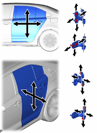
Using SST, loosen the 4 hinge bolts on the vehicle body and adjust the door position.
- SST
- 09812-00020
Tighten the 4 hinge bolts on the vehicle body after adjustment.
- Torque:
- 26 N*m (265 kgf*cm, 19 ft.*lbf)
Loosen the 4 hinge bolts on the door and adjust the door position.
Tighten the 4 hinge bolts on the door after adjustment.
- Torque:
- 21 N*m (214 kgf*cm, 15 ft.*lbf)
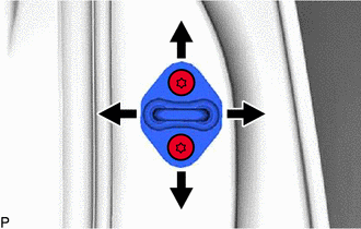
Using a T40 "TORX" socket wrench, slightly loosen the 2 striker mounting screws.
Using a brass bar and a hammer, hit the striker to adjust its position.
Using a T40 "TORX" socket wrench, tighten the 2 striker mounting screws after adjustment.
- Torque:
- 23 N*m (235 kgf*cm, 17 ft.*lbf)