RM3660EC
_58
Vehicle Interior
_080733
HEATING / AIR CONDITIONING
_0393741
SOLAR SENSOR
G
HEATING / AIR CONDITIONING SOLAR SENSOR ON-VEHICLE INSPECTION
PROCEDURE

 89120A
1.INSPECT AUTOMATIC LIGHT CONTROL SENSOR
89120A
1.INSPECT AUTOMATIC LIGHT CONTROL SENSOR
a.
1.542,0.25 1.875,0.5
0.333,0.25
0.906,1.688 1.406,1.188
true
1.635,1.698 1.615,1.208
true
0.354,0.26 0.667,0.417
0.313,0.156
10
false
*a
1.625,0.302 2.083,0.5
0.458,0.198
11
false
h1
1.479,1.719 2.094,1.917
0.615,0.198
10
false
CLTE
0.708,1.719 1.323,1.917
0.615,0.198
10
false
CLTB
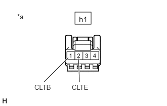
| *a | Front view of wire harness connector
(to Automatic Light Control Sensor) |
Disconnect the h1 automatic light control sensor connector.
b.
Measure the voltage and resistance according to the value(s) in the table below.
- Standard Voltage:
Tester Connection Condition Specified Condition *1: for HV Model
*2: for Gasoline Model
h1-1 (CLTB) - h1-2 (CLTE) Power switch off*1 Below 1 V Ignition switch off*2 Power switch on (IG)*1 11 to 14 V Ignition switch on (IG)*2
- Standard Resistance:
Tester Connection Condition Specified Condition h1-2 (CLTE) - Body ground Always Below 1 Ω
If the result is not as specified, there may be a malfunction on the wire harness side.
c.
Connect the h1 automatic light control sensor connector.
d.
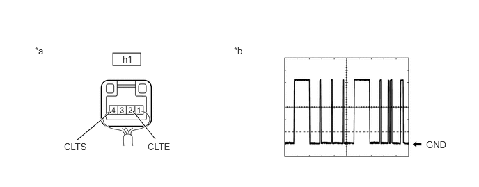
Connect an oscilloscope to terminals h1-2 (CLTE) and h1-4 (CLTS) of the automatic light control sensor connector and check the waveform.
1.688,0.792 2.104,0.979
0.417,0.188
1.156,2.094 1.656,1.677
true
2.323,2.083 1.99,1.667
true
0.521,0.677 0.833,0.833
0.313,0.156
10
false
*a
3.5,0.677 3.813,0.833
0.313,0.156
10
false
*b
1.833,0.802 2.292,1
0.458,0.198
10
false
h1
6.375,2.083 6.833,2.281
0.458,0.198
10
false
GND
0.958,2.115 1.406,2.313
0.448,0.198
10
false
CLTS
2.208,2.115 2.656,2.313
0.448,0.198
10
false
CLTE
| *a | Component with harness connected
(Automatic Light Control Sensor) |
*b | Waveform |
- OK:
Tester Connection Condition Tool Setting Specified Condition *1: for HV Model
*2: for Gasoline Model
h1-2 (CLTE) - h1-4 (CLTS) Power switch on (IG)*1 2 V/DIV., 10 ms./DIV. Pulse generation
(See waveform)Ignition switch on (IG)*2
- HINT:
-
The communication waveform changes according to the surrounding brightness.
If the result is not as specified, the automatic light control sensor may be malfunctioning.