RM3660EC
_58
Vehicle Interior
_080733
HEATING / AIR CONDITIONING
_0393737
ROOM TEMPERATURE SENSOR
G
HEATING / AIR CONDITIONING ROOM TEMPERATURE SENSOR INSPECTION
PROCEDURE

 88625Q
1.INSPECT COOLER (ROOM TEMP. SENSOR) THERMISTOR
88625Q
1.INSPECT COOLER (ROOM TEMP. SENSOR) THERMISTOR
a.
1.854,1.073 2.49,0.906
true
1.49,2.958 1.969,2.625
false
0.333,0.26 0.646,0.417
0.313,0.156
10
false
*a
2.542,0.813 2.854,0.969
0.313,0.156
10
false
*b
0.063,2.813 0.375,2.969
0.313,0.156
10
false
*c
1.771,4.333 2.083,4.49
0.313,0.156
10
false
*d
2.021,2.531 2.333,2.688
0.313,0.156
10
false
*e
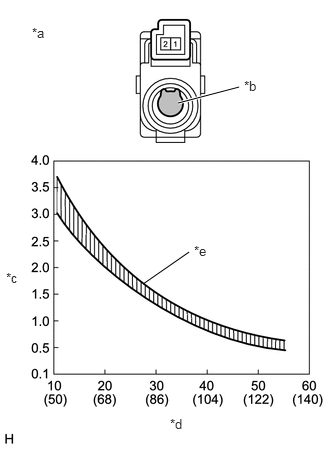
| *a | Component without harness connected
(Cooler (Room Temp. Sensor) Thermistor) |
| *b | Sensing Portion |
| *c | Resistance (kΩ) |
| *d | Temperature (°C (°F)) |
| *e | Allowable Range |
Measure the resistance according to the value(s) in the table below.
- Standard Resistance:
Tester Connection Condition Specified Condition 1 - 2 10°C (50°F) 3.00 to 3.73 kΩ 15°C (59°F) 2.45 to 2.88 kΩ 20°C (68°F) 1.95 to 2.30 kΩ 25°C (77°F) 1.60 to 1.80 kΩ 30°C (86°F) 1.28 to 1.47 kΩ 35°C (95°F) 1.00 to 1.22 kΩ 40°C (104°F) 0.80 to 1.00 kΩ 45°C (113°F) 0.65 to 0.85 kΩ 50°C (122°F) 0.50 to 0.70 kΩ 55°C (131°F) 0.44 to 0.60 kΩ 60°C (140°F) 0.36 to 0.50 kΩ
- NOTICE:
- ·
Hold the sensor only by its connector. Touching the sensing portion may change the resistance value.
·When measuring, the sensor temperature must be the same as the ambient temperature.
- HINT:
-
As the temperature increases, the resistance decreases (see the graph).
If the result is not as specified, replace the cooler (room temp. sensor) thermistor.