FRONT SUSPENSION FRONT STABILIZER BAR INSTALLATION
PROCEDURE

 48815E
1.INSTALL FRONT STABILIZER BAR BUSHING LH
48815E
1.INSTALL FRONT STABILIZER BAR BUSHING LH
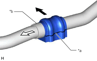
| *a | Cutout |
| *b | Stopper Ring |

|
Front of the Vehicle |

|
Outside of the Vehicle |
Install the front stabilizer bar bushing LH to the front stabilizer bar as shown in the illustration.
- NOTICE:
- ·
Install the front stabilizer bar bushing LH so that the cutout is facing the rear of the vehicle.
·Install the front stabilizer bar bushing LH onto the front stabilizer bar so that the stopper ring of the front stabilizer bar faces the outside of the vehicle.
48815D
2.INSTALL FRONT STABILIZER BAR BUSHING RH
- HINT:
-
Perform the same procedure as for the LH side.
48811
3.INSTALL FRONT STABILIZER BAR
Install the front stabilizer bar with the 2 front stabilizer bar bushings to the front suspension crossmember sub-assembly.
- NOTICE:
-
Make sure that the identification mark is positioned on the right side of the vehicle.
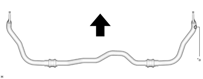
| *a | Identification Mark | - | - |
|
|
Front of the Vehicle | - | - |
48829A
4.INSTALL FRONT NO. 1 STABILIZER BRACKET LH
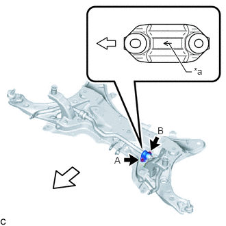
| *a | Arrow |
|
|
Front of the Vehicle |
Install the front No. 1 stabilizer bracket LH to the front suspension crossmember sub-assembly with the 2 bolts.
- Torque:
- 103 N*m (1050 kgf*cm, 76 ft.*lbf)
- NOTICE:
- ·
Make sure to install the front No. 1 stabilizer bracket LH with its arrow facing the front of the vehicle.
·Temporarily tighten the bolt (B) and then fully tighten the 2 bolts in the order of (A) and (B).
48824A
5.INSTALL FRONT NO. 1 STABILIZER BRACKET RH
- HINT:
-
Perform the same procedure as for the LH side.
48810
7.INSTALL FRONT STABILIZER LINK ASSEMBLY LH
Install the front stabilizer link assembly LH to the front shock absorber assembly with the nut.
- Torque:
- 74 N*m (755 kgf*cm, 55 ft.*lbf)
- HINT:
-
If the ball joint turns together with the nut, use a 6 mm hexagon socket wrench to hold the stud bolt.
48820B
8.INSTALL FRONT STABILIZER LINK ASSEMBLY RH
- HINT:
-
Perform the same procedure as for the LH side.
51201
9.INSTALL FRONT SUSPENSION CROSSMEMBER SUB-ASSEMBLY