NR Series INTAKE / EXHAUST TURBOCHARGER INSPECTION
PROCEDURE

 17201
1.INSPECT TURBOCHARGER SUB-ASSEMBLY
17201
1.INSPECT TURBOCHARGER SUB-ASSEMBLY
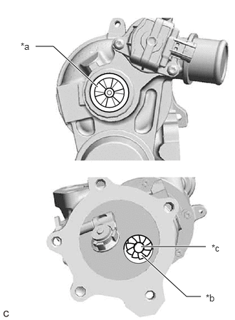
| *a | Compressor Side Impeller |
| *b | Exhaust Side Turbine |
| *c | Center of Exhaust Side Turbine |
Check if the compressor side impeller and exhaust side turbine are damaged or defective.
- HINT:
-
Wear on the center of the exhaust side turbine is not a malfunction.
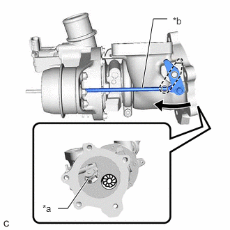
| *a | Waste Gate Valve |
| *b | Rod |
Move the rod by hand and check that the waste gate valve is not stuck.
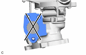
Using a straightedge and feeler gauge, check the turbocharger sub-assembly installation surface for warpage.
- Standard Warpage:
0.15 mm (0.00591 in.) or less
If the result is not as specified, replace the turbocharger sub-assembly.
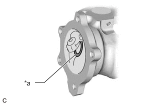
| *a | Contact Surface of Waste Gate Valve Port |
Close the waste gate valve and using a feeler gauge, measure the clearance between the waste gate valve and the contact surface of the valve port of the turbine with valve housing sub-assembly waste gate.
- Standard Clearance:
0.15 mm (0.00591 in.) or less
If the result is not as specified, replace the turbocharger sub-assembly.
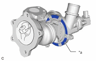
| *a | Area to be Checked |
Check the areas shown in the illustration for oil leakage.
- OK:
There are no oil leaks from the compressor with bearing housing sub-assembly.
- NOTICE:
-
Oil on the inlet side of the compressor is from oil in the blow-by gas and is not a malfunction.
If the result is not as specified, replace the turbocharger sub-assembly.
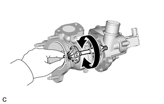
Rotate the compressor wheel by hand as shown in the illustration, and check that the compressor wheel rotates smoothly.
- OK:
Compressor wheel rotates smoothly.
- HINT:
-
If the compressor wheel does not rotate smoothly, replace the turbocharger sub-assembly.
Check that the turbine shaft rotates smoothly.
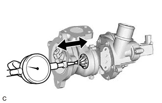
Set a dial indicator to the outlet side of the turbine shaft.
Move the turbine shaft in the axial direction and check for play.
- Standard Axial Play:
0.15 mm (0.00591 in.) or less
If the result is not as specified, replace the turbocharger sub-assembly.
2.INSPECT WASTE GATE VALVE ACTUATOR
Check the waste gate valve actuator hose for cracks and damage.
Check the waste gate valve actuator with bracket assembly air hole.
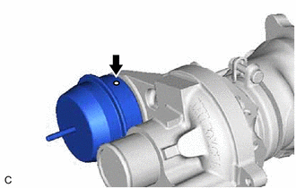
Check that the waste gate valve actuator air hole shown in the illustration is not clogged.
Check the waste gate valve actuator with bracket assembly travel.
Connect a vacuum pump to the waste gate valve actuator.
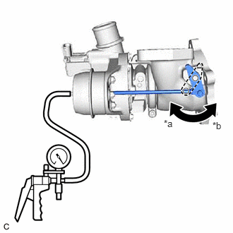
| *a | Vacuum at 30 kPa (225 mmHg, 8.8 in. Hg) |
| *b | Vacuum at 0 kPa (0 mmHg, 0 in. Hg) |
Using a vacuum pump, apply a vacuum of 30 +/- 4.0 kPa (225 +/- 30 mmHg, 8.8 +/- 1.2 in. Hg) to the diaphragm chamber to operate the waste gate valve actuator.
- OK:
The waste gate valve closes when vacuum is applied.
- NOTICE:
-
Do not apply a vacuum of 65 kPa (488 mmHg, 19.2 in. Hg) or more to the waste gate valve actuator as doing so may damage the diaphragm.
- HINT:
-
If the waste gate valve actuator does not operate, replace the turbocharger sub-assembly.
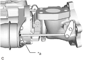
| *a | Paint Mark |
Place a paint mark on the waste gate valve actuator rod from the waste gate valve actuator bracket as shown in the illustration.
Using a vernier caliper, measure the distance from the waste gate valve actuator bracket to the paint mark at a vacuum of 0 kPa (0 mmHg, 0 in. Hg).
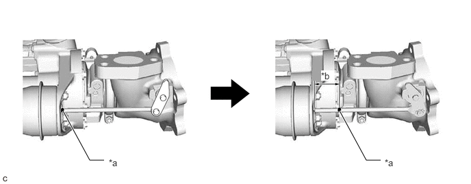
| *a | Paint Mark | *b | Travel of Waste Gate Valve Actuator |

|
Vacuum at 0 kPa (0 mmHg, 0 in. Hg) | - | - |
- Standard:
15 mm (0.591 in.) or more
If the result is not as specified, replace the turbocharger sub-assembly.
- NOTICE:
-
If the result is not as specified when replacing the turbocharger sub-assembly, and check the travel of the waste gate valve actuator again.
Disconnect the vacuum pump from the waste gate valve actuator.
3.INSPECT INTAKE AIR CONTROL VALVE (AIR BY-PASS VALVE ASSEMBLY)
Inspect the resistance.
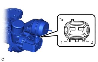
| *a | Component without harness connected
(Air By-pass Valve Assembly) |
Measure the resistance according to the value(s) in the table below.
- Standard Resistance:
Tester Connection Condition Specified Condition 1 - 2 20°C (68°F) 8.7 to 9.2 Ω
If the result is not as specified, replace the turbocharger sub-assembly.