NR Series ENGINE CONTROL MASS AIR FLOW METER INSPECTION
PROCEDURE

 22204
1.INSPECT MASS AIR FLOW METER SUB-ASSEMBLY
22204
1.INSPECT MASS AIR FLOW METER SUB-ASSEMBLY
Check the output voltage.
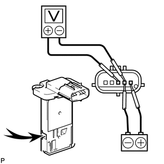
| *a | Component without harness connected
(Mass Air Flow Meter Sub-assembly) |

|
Air |
Connect a battery positive (+) lead to terminal 1 (+B) and negative (-) lead to terminal 2 (E2G).
- NOTICE:
-
While using the battery during inspection, do not bring the positive and negative tester probes too close to each other as a short circuit may occur.
Connect the positive (+) tester probe to terminal 3 (VG) and negative (-) tester probe to terminal 2 (E2G).
Blow air into the mass air flow meter sub-assembly and check that the voltage fluctuates.
- OK:
The voltage changes.
If the result is not as specified, replace the mass air flow meter sub-assembly.
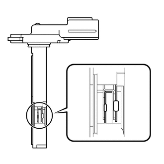
| *a | Platinum Hot Wire (Heater) |
| *b | Intake Air Temperature Sensor (Thermistor) |
Perform a visual check for any foreign matter on the platinum hot wire (heater) and intake air temperature sensor (thermistor) of the mass air flow meter sub-assembly shown in the illustration.
- OK:
There is no foreign matter.
If the result is not as specified, clean the mass air flow meter sub-assembly.
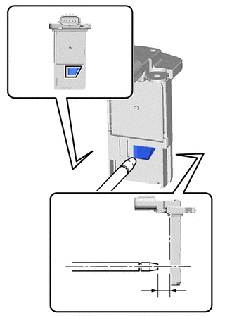
| *a | Air Blow Gun |
| *b | 10 mm (0.394 in.) |
| *c | Airflow Hole |
Clean the mass air flow meter sub-assembly.
- NOTICE:
- ·
Do not contact the mass air flow meter sub-assembly with the nozzle of the air blow gun.
·Do not insert the nozzle of the air blow gun into the airflow hole.
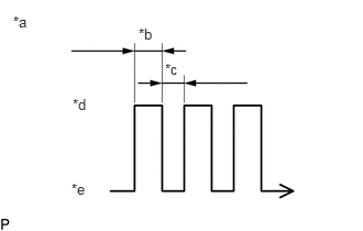
| *a | Air Blow Duration |
| *b | 3 to 6 Seconds |
| *c | 1 Second |
| *d | Air Blowing |
| *e | Air Stopped |
Using an air blow gun, clean the hole of the mass air flow meter sub-assembly by applying approximately 10 intermittent bursts of air to the airflow hole at a pressure of approximately 392 to 981 kPa (4.0 to 10.0 kgf/cm2, 57 to 142 psi).
- HINT:
-
After performing cleaning, read the value of Data List item "Mass Air Flow Sensor" using the GTS and if the value is not as specified, replace the mass air flow meter sub-assembly.
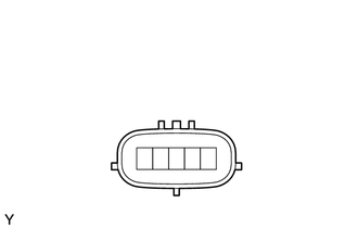
| *a | Component without harness connected
(Mass Air Flow Meter Sub-assembly) |
Check the intake air temperature sensor (thermistor) resistance.
Measure the resistance according to the value(s) in the table below.
- Standard Resistance:
Tester Connection Condition Specified Condition 4 (THA) - 5 (E2) Always 0.48 to 17.7 kΩ
If the result is not as specified, replace the mass air flow meter sub-assembly.