NR Series ENGINE CONTROL CAMSHAFT OIL CONTROL SOLENOID INSPECTION
PROCEDURE

 15370
1.INSPECT CAMSHAFT TIMING OIL CONTROL SOLENOID ASSEMBLY
15370
1.INSPECT CAMSHAFT TIMING OIL CONTROL SOLENOID ASSEMBLY
- HINT:
-
Use the same procedure for the intake side and exhaust side.
Check the resistance.
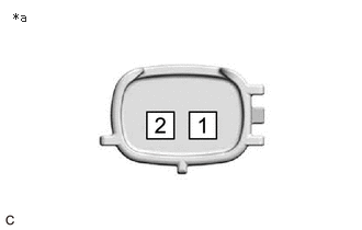
| *a | Component without harness connected
(Camshaft Timing Oil Control Solenoid Assembly) |
Measure the resistance according to the value(s) in the table below.
- Standard Resistance:
Tester Connection Condition Specified Condition 1 - 2 0°C (32°F) 5.3 to 6.3 Ω 20°C (68°F) 5.8 to 6.8 Ω 40°C (104°F) 6.2 to 7.4 Ω
If the result is not as specified, replace the camshaft timing oil control solenoid assembly.
Stroke Amount Inspection
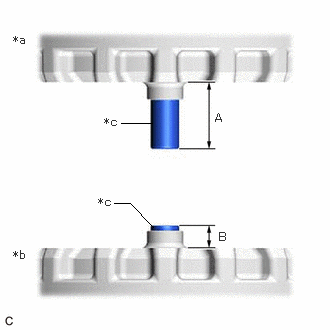
| *a | Shaft Side Facing Down |
| *b | Shaft Side Facing Up |
| *c | Shaft |
Using vernier calipers, measure length (A) and (B) with the shaft of the camshaft timing oil control solenoid assembly set in the respective positions shown in the illustration.
- NOTICE:
-
Do not apply battery voltage to the terminals of the camshaft timing oil control solenoid assembly.
- HINT:
-
If the shaft does not extend under its own weight, extend the shaft with your fingers.
Calculate the stroke amount based on the difference of length (A) and (B).
- Standard:
6.5 mm (0.256 in.) or more
- HINT:
-
Stroke amount = length (A) - length (B)
If the value is not as specified, replace the camshaft timing oil control solenoid assembly.