K313 CVT CONTINUOUSLY VARIABLE TRANSAXLE UNIT REASSEMBLY
CAUTION / NOTICE / HINT
- NOTICE:
- ·
Clean the work area, tools to be used, other equipment, etc., thoroughly before performing this procedure, as there is a possibility that a CVT malfunction, which may prevent the vehicle from being driven, may occur if dust or fine foreign matter enters the CVT.
·Do not use cotton work gloves, cloths, paper towels, etc., that may produce lint, dust or foreign matter.
·When cleaning parts, make sure that dust or foreign matter does not enter the CVT.
·When replacing any tapered roller bearing (inner race) or tapered roller bearing (outer race), replace both the tapered roller bearing (inner race) and tapered roller bearing (outer race) with new ones.
·When the tapered roller bearing (inner race) is removed, the tapered roller bearing (inner race) and tapered roller bearing (outer race) need to be replaced.
·When the tapered roller bearing (inner race) is not removed, the tapered roller bearing (inner race) and tapered roller bearing (outer race) can be reused.
PROCEDURE

 1. BEARING POSITION
Check the position and installation direction of each bearing.
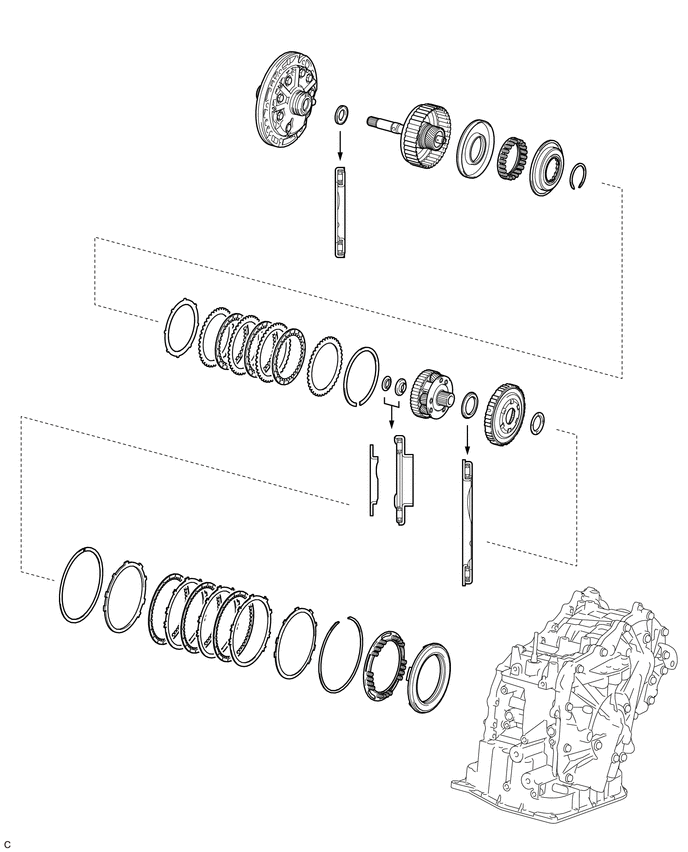
| Mark | Race Diameter
Inside / Outside (mm (in.)) |
Thrust Bearing Diameter
Inside / Outside (mm (in.)) |
|---|---|---|
| A | - | 20.7 mm (0.815 in.) / 36.5 mm (1.44 in.) |
| B | 17.0 mm (0.669 in.) / 28.0 mm (1.10 in.) | 16.6 mm (0.654 in.) / 31.7 mm (1.25 in.) |
| C | - | 34.5 mm (1.36 in.) / 51.5 mm (2.03 in.) |
41211B
2.INSTALL FRONT DRIVE PINION REAR TAPERED ROLLER BEARING (OUTER RACE)
- HINT:
-
When the front drive pinion rear tapered roller bearing (inner race) is not removed, the front drive pinion rear tapered roller bearing (inner race) and front drive pinion rear tapered roller bearing (outer race) can be reused.
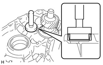
Using SST and a hammer, install a new front drive pinion rear tapered roller bearing (outer race) to the transaxle case.
- SST
- 09950-60011 (09951-00460, 09951-00580, 09952-06010)
09950-70010 (09951-07100)
- NOTICE:
-
Be sure to install the front drive pinion rear tapered roller bearing (outer race) so that there is no clearance between it and the transaxle case. If there is any clearance, the turning torque of the reduction driven gear cannot be measured correctly.
41311F
3.INSTALL FRONT DIFFERENTIAL CASE REAR TAPERED ROLLER BEARING (OUTER RACE)
- HINT:
-
When the front differential case rear tapered roller bearing (inner race) is not removed, the front differential case rear tapered roller bearing (inner race) and front differential case rear tapered roller bearing (outer race) can be reused.
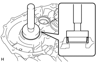
Using SST and a hammer, install a new front differential case rear tapered roller bearing (outer race) to the transaxle case.
- SST
- 09950-60011 (09951-00650, 09952-06010)
09950-60021 (09951-00750)
09950-70010 (09951-07100)
- NOTICE:
-
Be sure to install the front differential case rear tapered roller bearing (outer race) so that there is no clearance between it and the transaxle case. If there is any clearance, the turning torque of the front differential case sub-assembly cannot be measured correctly.
41211A
4.INSTALL FRONT DRIVE PINION FRONT TAPERED ROLLER BEARING (OUTER RACE)
- HINT:
-
When the front drive pinion front tapered roller bearing (inner race) is not removed, the front drive pinion front tapered roller bearing (inner race) and front drive pinion front tapered roller bearing (outer race) can be reused.
Install the shim to the transaxle housing.
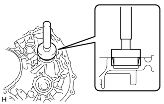
Using SST and a hammer, install a new front drive pinion front tapered roller bearing (outer race) to the transaxle housing.
- SST
- 09950-60011 (09951-00420, 09951-00550, 09952-06010)
09950-70010 (09951-07100)
- NOTICE:
-
Be sure to install the front drive pinion front tapered roller bearing (outer race) so that there is no clearance between it and the transaxle housing. If there is any clearance, the turning torque of the reduction driven gear cannot be measured correctly.
41311E
5.INSTALL FRONT DIFFERENTIAL CASE FRONT TAPERED ROLLER BEARING (OUTER RACE)
- HINT:
-
When the front differential case front tapered roller bearing (inner race) is not removed, the front differential case front tapered roller bearing (inner race) and front differential case front tapered roller bearing (outer race) can be reused.
Install the shim to the transaxle housing.
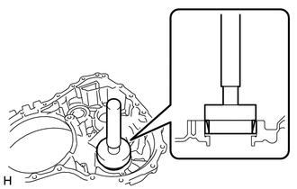
Using SST and a hammer, install a new front differential case front tapered roller bearing (outer race) to the transaxle housing.
- SST
- 09950-60011 (09951-00560, 09952-06010)
09950-60021 (09951-00680)
09950-70010 (09951-07100)
- NOTICE:
-
Be sure to install the front differential case front tapered roller bearing (outer race) so that there is no clearance between the shim and transaxle housing. If there is any clearance, the turning torque of the front differential case sub-assembly cannot be measured correctly.
41311F
6.INSTALL FRONT DIFFERENTIAL CASE REAR TAPERED ROLLER BEARING (INNER RACE)
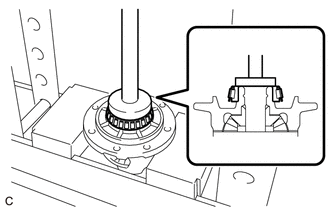
Using SST and a press, install a new front differential case rear tapered roller bearing (inner race) to the front differential case sub-assembly.
- SST
- 09950-60011 (09951-00570)
09950-70010 (09951-07100)
- NOTICE:
-
Be sure to install the front differential case rear tapered roller bearing (inner race) so that there is no clearance between it and the front differential case sub-assembly. If there is any clearance, the turning torque of the front differential case sub-assembly cannot be measured correctly.
41311E
7.INSTALL FRONT DIFFERENTIAL CASE FRONT TAPERED ROLLER BEARING (INNER RACE)
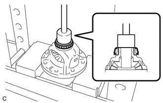
Using SST and a press, install a new front differential case front tapered roller bearing (inner race) to the front differential case sub-assembly.
- SST
- 09710-22021 (09710-01031)
09950-70010 (09951-07100)
- NOTICE:
-
Be sure to install the front differential case front tapered roller bearing (inner race) so that there is no clearance between it and the front differential case sub-assembly. If there is any clearance, the turning torque of the front differential case sub-assembly cannot be measured correctly.
41221
8.INSTALL FRONT DIFFERENTIAL RING GEAR
- HINT:
-
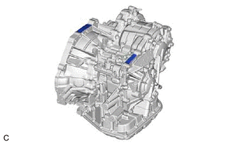 0.958,0.375 1.24,0.427 false 2.01,0.906 2.688,1.042 true 0.74,0.271 1,0.583 0.26,0.313 10 false *a 2.781,1.01 3.094,1.208 0.313,0.198 10 false *b
*a TMH Made *b TMCAP Made
-
TMH Made and TMCAP Made components can be identified by the location where the serial number is stamped.
Using Toyota Genuine CVT fluid FE and a heater, heat the front differential ring gear to between 90 to 110°C (194 to 230°F).
- CAUTION:
-
Be careful not to burn yourself when the fluid temperature is high.
- NOTICE:
-
Do not heat the front differential ring gear to more than 110°C (230°F).
Clean the contact surface of the front differential case sub-assembly.
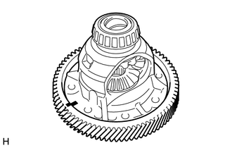
| *a | Matchmark |
Align the matchmarks, and install the front differential ring gear to the front differential case sub-assembly quickly.
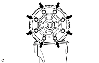
Secure the front differential ring gear in a vise between aluminum plates.
- NOTICE:
- ·
Do not overtighten the vise.
·Be careful not to drop the front differential case sub-assembly.
Install 8 new bolts.
- Torque:
- for TMH Made : 120 N*m (1224 kgf*cm, 89 ft.*lbf)
- for TMCAP Made : 110 N*m (1122 kgf*cm, 81 ft.*lbf)
- NOTICE:
- ·
The new bolts are coated with heat resistant oil. Do not clean off this coating.
·Install the bolts after the front differential ring gear has cooled down sufficiently.
·Tighten the bolts evenly in a diagonal pattern using several steps.
9.ADJUST DIFFERENTIAL SIDE BEARING PRELOAD
- HINT:
-
The front differential case front tapered roller bearing (outer race) can be reused when performing adjustment.
Remove any seal packing from the contact surfaces between the transaxle case and transaxle housing.
- NOTICE:
-
Make sure that there is no Toyota Genuine CVT fluid FE on the contact surfaces.
Clean and degrease the 22 bolts and installation holes of the transaxle case.
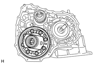
Install the front differential case sub-assembly to the transaxle case.
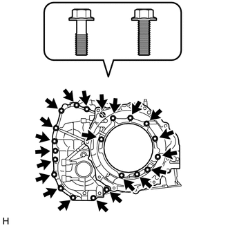
| *a | Bolt (A) |
| *b | Bolt (B) |
Install the transaxle housing to the transaxle case with the 22 bolts.
- Torque:
- 29.4 N*m (300 kgf*cm, 22 ft.*lbf)
- NOTICE:
-
Be careful of the difference between bolt (A) and bolt (B) when installing the bolts.
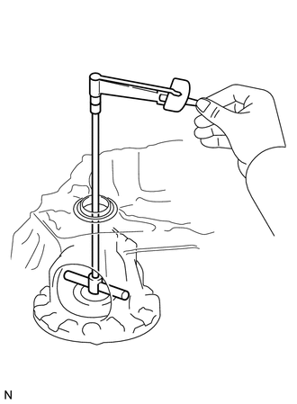
Using SST, turn the front differential case sub-assembly right and left 2 or 3 times to settle the bearings.
- SST
- 09564-32011
Using SST and a torque wrench, measure the turning torque of the front differential case sub-assembly while rotating SST at 10 rpm.
- SST
- 09564-32011
- Turning Torque:
0.74 to 1.41 N*m (8 to 14 kgf*cm, 7 to 12 in.*lbf)
If the turning torque is not within the specified range, refer to the table below to select a shim so that the turning torque is within the specified range.
- Shim Thickness:
Mark Thickness Mark Thickness A 2.03 mm (0.0799 in.) L 2.33 mm (0.0917 in.) B 2.06 mm (0.0811 in.) M 2.36 mm (0.0929 in.) C 2.09 mm (0.0823 in.) N 2.39 mm (0.0941 in.) D 2.12 mm (0.0835 in.) P 2.42 mm (0.0953 in.) E 2.15 mm (0.0846 in.) Q 2.45 mm (0.0965 in.) F 2.18 mm (0.0858 in.) R 2.48 mm (0.0976 in.) G 2.21 mm (0.0870 in.) S 2.51 mm (0.0988 in.) H 2.24 mm (0.0882 in.) T 2.54 mm (0.100 in.) J 2.27 mm (0.0894 in.) U 2.57 mm (0.101 in.) K 2.30 mm (0.0906 in.) V 2.60 mm (0.102 in.)
- HINT:
-
There are 20 shims of different thicknesses.
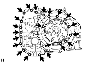
Remove the 22 bolts and the transaxle housing from the transaxle case.
10.INSTALL REDUCTION DRIVEN GEAR LOCK NUT
- HINT:
-
Perform this procedure only when replacement of the reduction driven gear is necessary.
Mount the reduction driven gear in a vise between aluminum plates.
- NOTICE:
-
Be careful not to damage the reduction driven gear.
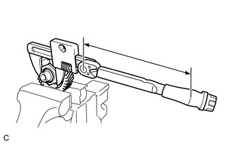
| *a | Torque Wrench Fulcrum Length |
Using SST, install a new reduction driven gear lock nut to the reduction driven gear.
- SST
- 09922-10010
- Torque:
- Specified Tightening Torque : 160 N*m (1632 kgf*cm, 118 ft.*lbf)
- HINT:
- ·
Calculate the torque wrench reading when changing the fulcrum length of the torque wrench.
·When using SST (fulcrum length of 126 mm (4.96 in.)) + torque wrench (fulcrum length of 400 mm (15.7 in.)):
121.7 N*m (1241 kgf*cm, 90 ft.*lbf)
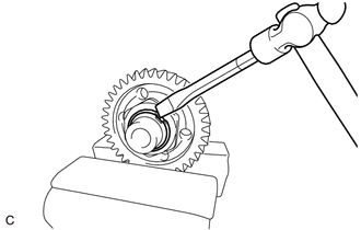
Using a chisel and hammer, stake the reduction driven gear lock nut.
- NOTICE:
-
Be careful not to damage the reduction driven gear.
41211B
11.INSTALL FRONT DRIVE PINION REAR TAPERED ROLLER BEARING (INNER RACE)
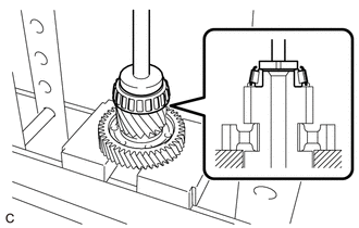
Using SST and a press, install a new front drive pinion rear tapered roller bearing (inner race) to the reduction driven gear.
- SST
- 09950-60011 (09951-00360)
09950-70010 (09951-07100)
- NOTICE:
-
Be sure to install the front drive pinion rear tapered roller bearing (inner race) so that there is no clearance between it and the reduction driven gear. If there is any clearance, the turning torque of the reduction driven gear cannot be measured correctly.
41211A
12.INSTALL FRONT DRIVE PINION FRONT TAPERED ROLLER BEARING (INNER RACE)
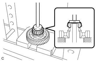
Using SST and a press, install a new front drive pinion front tapered roller bearing (inner race) to the reduction driven gear.
- SST
- 09950-60011 (09951-00320)
09950-70010 (09951-07100)
- NOTICE:
-
Be sure to install the front drive pinion front tapered roller bearing (inner race) so that there is no clearance between it and the reduction driven gear. If there is any clearance, the turning torque of the reduction driven gear cannot be measured correctly.
13.ADJUST REDUCTION DRIVEN GEAR SIDE BEARING PRELOAD
- HINT:
-
The front drive pinion front tapered roller bearing (outer race) can be reused when performing adjustment.
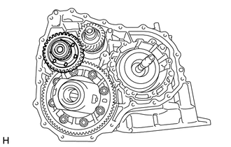
Install the reduction driven gear to the transaxle case.
| *a | Bolt (A) |
| *b | Bolt (B) |
Install the transaxle housing to the transaxle case with the 22 bolts.
- Torque:
- 29.4 N*m (300 kgf*cm, 22 ft.*lbf)
- NOTICE:
-
Be careful of the difference between bolt (A) and bolt (B) when installing the bolts.
Using SST, turn the front differential case sub-assembly right and left 2 or 3 times to settle the bearings.
- SST
- 09564-32011
Using SST and a torque wrench, measure the turning torque while rotating SST at 10 rpm.
- SST
- 09564-32011
- Turning Torque:
Differential side bearing preload + 2.24 to 4.48 N*m (23 to 45 kgf*cm, 20 to 39 in.*lbf)
If the turning torque is not within the specified range, refer to the table below to select a shim so that the turning torque is within the specified range.
- Shim Thickness:
Mark Thickness Mark Thickness A 1.73 mm (0.0681 in.) L 2.03 mm (0.0799 in.) B 1.76 mm (0.0693 in.) M 2.06 mm (0.0811 in.) C 1.79 mm (0.0705 in.) N 2.09 mm (0.0823 in.) D 1.82 mm (0.0717 in.) P 2.12 mm (0.0835 in.) E 1.85 mm (0.0728 in.) Q 2.15 mm (0.0846 in.) F 1.88 mm (0.0740 in.) R 2.18 mm (0.0858 in.) G 1.91 mm (0.0752 in.) S 2.21 mm (0.0870 in.) H 1.94 mm (0.0764 in.) T 2.24 mm (0.0882 in.) J 1.97 mm (0.0776 in.) U 2.27 mm (0.0894 in.) K 2.00 mm (0.0787 in.) - -
- HINT:
-
There are 19 shims of different thicknesses.
Remove the 22 bolts and the transaxle housing from the transaxle case.
Remove the reduction driven gear and front differential case sub-assembly from the transaxle case.
35882E
14.INSTALL NO. 1 DIFFERENTIAL GEAR LUBE APPLY TUBE
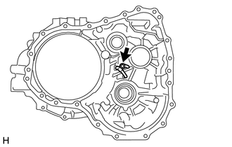
Install the No. 1 differential gear lube apply tube to the transaxle housing.
- NOTICE:
-
Insert the No. 1 differential gear lube apply tube into the transaxle housing until it makes contact with the stopper.
Install the No. 1 transaxle apply tube clamp to the No. 1 differential gear lube apply tube.
- NOTICE:
-
There should be clearance between the No. 1 differential gear lube apply tube and No. 1 transaxle apply tube clamp.
Install the bolt.
- Torque:
- 8.0 N*m (82 kgf*cm, 71 in.*lbf)
35174B
15.INSTALL OIL RESERVOIR LOCK PLATE
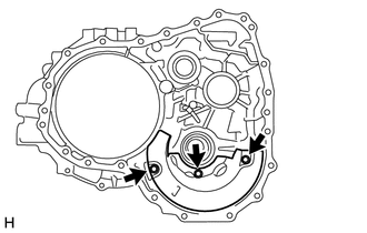
Install the oil reservoir lock plate to the transaxle housing with the 3 bolts.
- Torque:
- 8.0 N*m (82 kgf*cm, 71 in.*lbf)
35623L
16.INSTALL REVERSE BRAKE PISTON
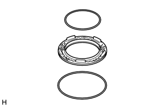
Coat 2 new O-rings with Toyota Genuine CVT fluid FE and install them to the reverse brake piston.
- NOTICE:
-
Ensure that the O-rings are not twisted.
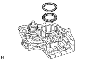
Install the reverse brake piston and 1st and reverse brake return spring sub-assembly to the transaxle case.
- NOTICE:
-
Be careful not to damage the O-rings.
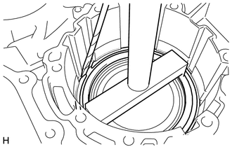
| *a | Protective Tape |
Using SST and a screwdriver, compress the 1st and reverse brake return spring sub-assembly and install the snap ring to the transaxle case.
- SST
- 09350-36010 (09350-06030)
09950-70010 (09951-07100)
- NOTICE:
-
Be careful not to damage the transaxle case.
- HINT:
-
Tape the screwdriver tip before use.
35681B
17.INSPECT NO. 1 BRAKE DISC
35681B
18.INSTALL NO. 1 BRAKE DISC
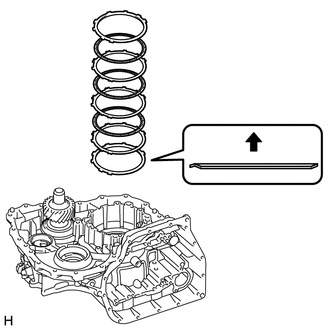
| *1 | Brake Flange |
| *2 | No. 1 Brake Disc |
| *3 | No. 1 Brake Plate |
| *4 | Brake Cushion Plate |
Install the brake flange, 3 No. 1 brake discs, 3 No. 1 brake plates and brake cushion plate to the transaxle case.
- NOTICE:
- ·
Make sure that the brake flange, No. 1 brake discs, No. 1 brake plates and brake cushion plate are installed in the correct order.
·Be sure to install the brake cushion plate in the correct direction.
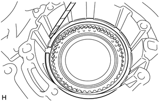
| *a | Protective Tape |
Using a screwdriver, install the snap ring to the transaxle case.
- NOTICE:
-
Be careful not to damage the transaxle case.
- HINT:
-
Tape the screwdriver tip before use.
35681B
19.INSPECT CLEARANCE OF NO. 1 BRAKE DISC
35075D
20.INSTALL FRONT PLANETARY RING GEAR SUB-ASSEMBLY
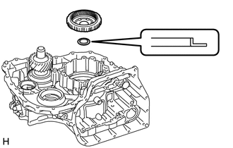
Coat the thrust washer with Toyota Genuine CVT fluid FE, and install it to the front planetary ring gear sub-assembly.
- NOTICE:
-
Be sure to install the thrust washer in the correct direction.
Install the front planetary ring gear sub-assembly to the transaxle case.
35720M
21.INSPECT PLANETARY GEAR ASSEMBLY
35720M
22.INSTALL PLANETARY GEAR ASSEMBLY
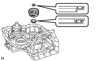
| *1 | Thrust Needle Roller Bearing (B) |
| *2 | Thrust Needle Roller Bearing (C) |
Coat the 2 thrust needle roller bearings with Toyota Genuine CVT fluid FE and install them to the planetary gear assembly.
- Thrust Needle Roller Bearing Diameter:
- Inside Outside Thrust needle roller bearing (B) 16.6 mm (0.654 in.) 31.7 mm (1.25 in.) Thrust needle roller bearing (C) 34.5 mm (1.36 in.) 51.5 mm (2.03 in.)
- NOTICE:
-
Be sure to install the thrust needle roller bearing in the correct direction.
Install the planetary gear assembly to the transaxle case.
35612D
23.INSTALL FORWARD CLUTCH PISTON
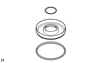
Coat 2 new O-rings with Toyota Genuine CVT fluid FE and install them to the forward clutch piston.
- NOTICE:
-
Ensure that the O-rings are not twisted.
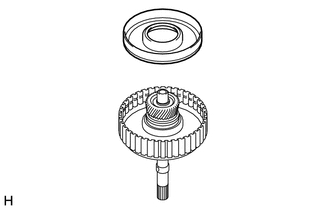
Install the forward clutch piston to the input shaft sub-assembly.
- NOTICE:
-
Be careful not to damage the O-rings.
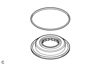
Coat a new O-ring with Toyota Genuine CVT fluid FE and install it to the No. 1 clutch balancer.
- NOTICE:
-
Ensure that the O-ring is not twisted.
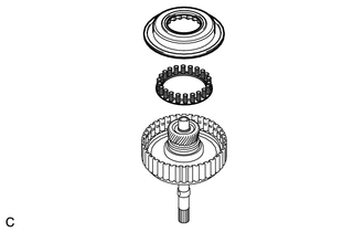
Install the forward clutch return spring sub-assembly and No. 1 clutch balancer to the input shaft sub-assembly.
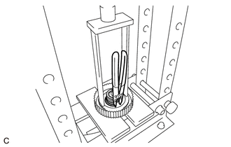
Place SST on the No. 1 clutch balancer and compress the forward clutch return spring sub-assembly with a press.
- SST
- 09387-00020
- NOTICE:
- ·
Stop the press when the forward clutch return spring sub-assembly is lowered to 1 to 2 mm (0.0394 to 0.0787 in.) from the snap ring groove to prevent the forward clutch return spring sub-assembly from being deformed.
·Be careful not to damage the O-ring.
Using a snap ring expander, install the snap ring.
- NOTICE:
- ·
Be sure that the end gap of the snap ring is not aligned with the spring retainer claw.
·Do not expand the snap ring excessively.
35633H
24.INSPECT FORWARD MULTIPLE DISC CLUTCH CLUTCH DISC
35633H
25.INSTALL FORWARD MULTIPLE DISC CLUTCH CLUTCH DISC
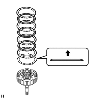
| *1 | Forward Clutch Flange |
| *2 | Forward Multiple Disc Clutch Clutch Disc |
| *3 | Forward Multiple Disc Clutch Clutch Plate |
| *4 | Clutch Cushion Plate |
Install the forward clutch flange, 3 forward multiple disc clutch clutch discs, 3 forward multiple disc clutch clutch plates and clutch cushion plate to the input shaft sub-assembly.
- NOTICE:
- ·
Make sure that the forward clutch flange, forward multiple disc clutch clutch discs, forward multiple disc clutch clutch plates and clutch cushion plate are installed in the correct order.
·Be sure to install the clutch cushion plate in the correct direction.
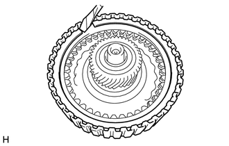
| *a | Protective Tape |
Using a screwdriver, install the snap ring to the input shaft sub-assembly.
- NOTICE:
-
Be careful not to damage the input shaft sub-assembly.
- HINT:
-
Tape the screwdriver tip before use.
35633H
26.INSPECT CLEARANCE OF FORWARD MULTIPLE DISC CLUTCH CLUTCH DISC
27.INSTALL INPUT SHAFT SUB-ASSEMBLY
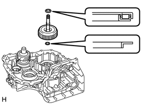
| *1 | Thrust Needle Roller Bearing (A) |
| *2 | Thrust Bearing Race (B) |
Coat the thrust needle roller bearing and thrust bearing race with Toyota Genuine CVT fluid FE and install them to the input shaft sub-assembly.
- Thrust Needle Roller Bearing and Race Diameter:
- Inside Outside Thrust needle roller bearing (A) 20.7 mm (0.815 in.) 36.5 mm (1.44 in.) Thrust bearing race (B) 17.0 mm (0.669 in.) 28.0 mm (1.10 in.)
- NOTICE:
-
Be sure to install the thrust needle roller bearing and thrust bearing race in the correct direction.
Install the input shaft sub-assembly to the transaxle case.
35882E
28.INSTALL NO. 2 DIFFERENTIAL GEAR LUBE APPLY TUBE

Install the No. 2 differential gear lube apply tube to the transaxle case.
- NOTICE:
-
Insert the No. 2 differential gear lube apply tube into the transaxle case until it makes contact with the stopper.
Install the No. 2 transaxle apply tube clamp to the No. 2 differential gear lube apply tube.
- NOTICE:
-
There should be clearance between the No. 2 differential gear lube apply tube and No. 2 transaxle apply tube clamp.
Install the bolt.
- Torque:
- 5.4 N*m (55 kgf*cm, 48 in.*lbf)
35165B
29.INSTALL NO. 1 TRANSMISSION CASE PLATE
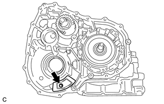
Install the No. 1 transmission case plate to the transaxle case with the bolt.
- Torque:
- 5.4 N*m (55 kgf*cm, 48 in.*lbf)
41302F
30.INSTALL FRONT DIFFERENTIAL CASE SUB-ASSEMBLY
Install the front differential case sub-assembly to the transaxle case.
35759A
31.INSTALL REDUCTION DRIVEN GEAR
Install the reduction driven gear to the transaxle case.
35111C
32.INSTALL TRANSAXLE HOUSING
Clean and degrease the contact surfaces of the transaxle housing and transaxle case.
- NOTICE:
-
Make sure that there is no Toyota Genuine CVT fluid FE on the contact surfaces.
Clean and degrease the 22 bolts and installation holes of the transaxle case.
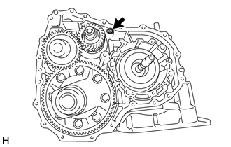
Coat a new O-ring with Toyota Genuine CVT fluid FE and install it to the transaxle case.
- NOTICE:
-
Ensure that the O-ring is not twisted.
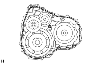
| *a | Seal Packing |
Apply seal packing to the transaxle case.
- Seal Packing:
Toyota Genuine Seal Packing 1281, Three Bond 1281 or equivalent
- NOTICE:
- ·
Apply seal packing in a continuous line (width 1.2 mm (0.0472 in.)) along the sealing surface.
·After applying seal packing, install the transaxle housing to the transaxle case within 3 minutes and tighten the bolts within 10 minutes.
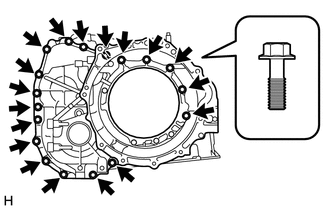
Install the transaxle housing to the transaxle case with the 18 bolts.
- Torque:
- 29.4 N*m (300 kgf*cm, 22 ft.*lbf)
- NOTICE:
-
Be careful of the type of bolts being used.
Apply adhesive to 2 or 3 threads on the ends of the 4 bolts.
- Adhesive:
Toyota Genuine Adhesive 1324, Three Bond 1324 or equivalent
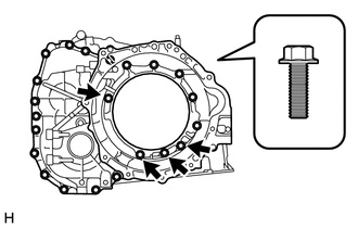
Install the 4 bolts.
- Torque:
- 29.4 N*m (300 kgf*cm, 22 ft.*lbf)
- NOTICE:
-
Be careful of the type of bolts being used.
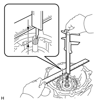
Using a vernier caliper and straightedge, measure the dimension (A) shown in the illustration.
- Standard:
24.0 to 24.8 mm (0.945 to 0.976 in.)
- HINT:
-
Make sure to deduct the thickness of the straightedge.
35310A
33.INSTALL FRONT OIL PUMP ASSEMBLY
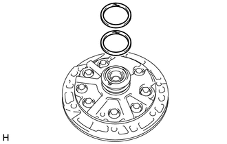
Coat 2 new oil seal rings with Toyota Genuine CVT fluid FE and install them to the front oil pump assembly.
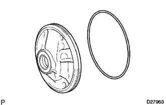
Coat a new O-ring with Toyota Genuine CVT fluid FE and install it to the front oil pump assembly.
- NOTICE:
-
Ensure that the O-ring is not twisted.
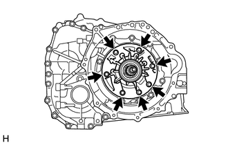
Install the front oil pump assembly to the continuously variable transaxle assembly with the 7 bolts.
- Torque:
- 29.4 N*m (300 kgf*cm, 22 ft.*lbf)
- NOTICE:
-
Be careful not to damage the O-ring.
35145D
34.INSTALL TRANSAXLE CASE GASKET
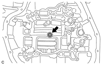
Coat a new transaxle case gasket with Toyota Genuine CVT fluid FE and install it to the continuously variable transaxle assembly.
89413N
35.INSTALL TRANSMISSION REVOLUTION SENSOR (NT)
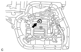
Install the transmission revolution sensor (NT) to the continuously variable transaxle assembly with the bolt.
- Torque:
- 5.4 N*m (55 kgf*cm, 48 in.*lbf)
82125M
36.INSTALL TRANSMISSION WIRE
35410J
37.INSTALL TRANSMISSION VALVE BODY ASSEMBLY
35330D
38.INSTALL OIL STRAINER ASSEMBLY
35394D
39.INSTALL OIL CLEANER (CVT) MAGNET
35106L
40.INSTALL TRANSAXLE OIL (CVT) PAN SUB-ASSEMBLY
Clean the transaxle oil (CVT) pan sub-assembly installation surface of the continuously variable transaxle assembly.
Install a new transaxle oil pan (CVT) gasket to the transaxle oil (CVT) pan sub-assembly.
When using the precoated bolt:
Clean and degrease the 16 bolts and installation holes in the continuously variable transaxle assembly.
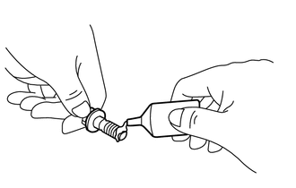
| *a | Adhesive |
Apply adhesive to 2 or 3 threads on the ends of the 16 bolts.
- Adhesive:
Toyota Genuine Adhesive 1324, Three Bond 1324 or equivalent
- NOTICE:
-
In order to ensure proper sealing of the 16 bolts, apply adhesive to the 16 bolts and install them within 10 minutes of applying adhesive.
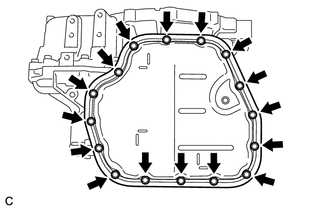
Install the transaxle oil (CVT) pan sub-assembly to the continuously variable transaxle assembly with the 16 bolts.
- Torque:
- 7.0 N*m (71 kgf*cm, 62 in.*lbf)
- NOTICE:
- ·
Make sure that there is no oil or foreign matter on the gasket seal surface or transaxle oil (CVT) pan sub-assembly contact surface.
·Make sure that the transmission wire is not pinched.
When using the Non-precoated bolt:
Install the transaxle oil (CVT) pan sub-assembly to the continuously variable transaxle assembly with the 16 bolts.
- Torque:
- 7.8 N*m (80 kgf*cm, 69 in.*lbf)
- NOTICE:
- ·
Make sure that there is no oil or foreign matter on the gasket seal surface or transaxle oil (CVT) pan sub-assembly contact surface.
·Make sure that the transmission wire is not pinched.
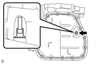
Using a 6 mm hexagon socket wrench, install the overflow (CVT) tube to the transaxle oil (CVT) pan sub-assembly.
- Torque:
- 1.7 N*m (17 kgf*cm, 15 in.*lbf)
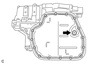
Using a 6 mm hexagon socket wrench, install a new gasket and the overflow plug to the transaxle oil (CVT) pan sub-assembly.
- Torque:
- 40 N*m (408 kgf*cm, 30 ft.*lbf)
41.INSTALL REFILL PLUG
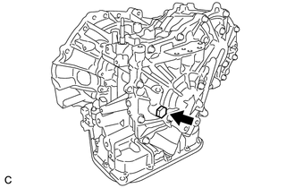
Install a new gasket and the refill plug to the continuously variable transaxle assembly.
- Torque:
- 49 N*m (500 kgf*cm, 36 ft.*lbf)
42.INSTALL STRAIGHT SCREW PLUG
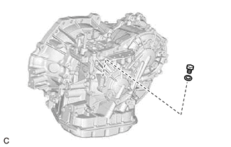
Install the straight screw plug and a new gasket to the continuously variable transaxle assembly.
- Torque:
- 16.2 N*m (165 kgf*cm, 12 ft.*lbf)
43.INSTALL NO. 1 TRANSAXLE CASE PLUG
Coat 4 new O-rings with Toyota Genuine CVT fluid FE and install them to the 4 No. 1 transaxle case plugs.
- NOTICE:
-
Ensure that the O-rings are not twisted.
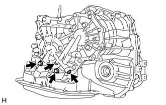
Install the 4 No. 1 transaxle case plugs to the continuously variable transaxle assembly.
- Torque:
- 7.4 N*m (75 kgf*cm, 65 in.*lbf)
- NOTICE:
-
Be careful not to damage the O-rings.
Coat 2 new O-rings with Toyota Genuine CVT fluid FE and install them to the 2 No. 1 transaxle case plugs.
- NOTICE:
-
Ensure that the O-rings are not twisted.
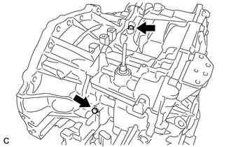
Install the 2 No. 1 transaxle case plugs to the continuously variable transaxle assembly.
- Torque:
- 7.4 N*m (75 kgf*cm, 65 in.*lbf)
- NOTICE:
-
Be careful not to damage the O-rings.
44.INSTALL TRANSAXLE HOUSING PLUG
Coat 2 new O-rings with Toyota Genuine CVT fluid FE and install them to the 2 transaxle housing plugs.
- NOTICE:
-
Ensure that the O-rings are not twisted.
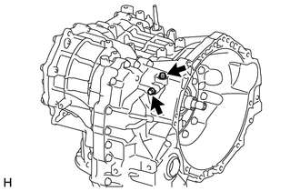
Install the 2 transaxle housing plugs to the continuously variable transaxle assembly.
- Torque:
- 7.4 N*m (75 kgf*cm, 65 in.*lbf)
- NOTICE:
-
Be careful not to damage the O-rings.
33493C
45.INSTALL TRANSMISSION OIL COOLER
Apply Toyota Genuine CVT fluid FE to 2 new O-rings, and install them to the transmission oil cooler.
Install the transmission oil cooler to the continuously variable transaxle assembly with the 3 bolts.
- Torque:
- 21 N*m (214 kgf*cm, 15 ft.*lbf)
- NOTICE:
-
Be careful not to damage the O-rings.
89637K
46.INSTALL OIL PRESSURE SENSOR
Coat the O-ring of the oil pressure sensor with Toyota Genuine CVT fluid FE.
- NOTICE:
-
If reusing the oil pressure sensor, check that the O-ring is not damaged.
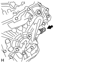
Using a 27 mm deep socket wrench, install the oil pressure sensor to the continuously variable transaxle assembly.
- Torque:
- 20.6 N*m (210 kgf*cm, 15 ft.*lbf)
- NOTICE:
-
Be careful not to damage the O-ring.
89413M
47.INSTALL TRANSMISSION REVOLUTION SENSOR (NOUT)
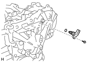
Coat a new O-ring with Toyota Genuine CVT fluid FE and install it to the transmission revolution sensor (NOUT).
- NOTICE:
-
Ensure that the O-ring is not twisted.
Install the transmission revolution sensor (NOUT) to the continuously variable transaxle assembly with the bolt.
- Torque:
- 5.4 N*m (55 kgf*cm, 48 in.*lbf)
- NOTICE:
-
Be careful not to damage the O-ring.
89413P
48.INSTALL TRANSMISSION REVOLUTION SENSOR (NIN)
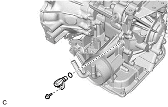
Coat a new O-ring with Toyota Genuine CVT fluid FE and install it to the transmission revolution sensor (NIN).
- NOTICE:
-
Ensure that the O-ring is not twisted.
Install the transmission revolution sensor (NIN) to the continuously variable transaxle assembly with the bolt.
- Torque:
- 5.4 N*m (55 kgf*cm, 48 in.*lbf)
- NOTICE:
-
Be careful not to damage the O-ring.
84540
49.INSTALL PARK/NEUTRAL POSITION SWITCH ASSEMBLY
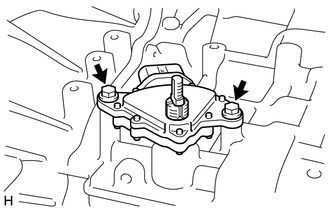
Temporarily install the park/neutral position switch assembly to the continuously variable transaxle assembly with the 2 bolts.
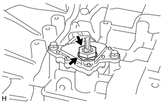
Install the lock plate and lock nut to the park/neutral position switch assembly.
- Torque:
- 6.9 N*m (70 kgf*cm, 61 in.*lbf)
Temporarily install the transmission control shaft lever to the park/neutral position switch assembly.
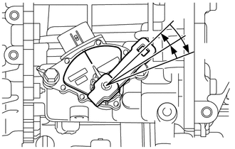
| *a | P Position |
| *b | N Position |
Turn the transmission control shaft lever clockwise until it stops, then turn it counterclockwise 2 notches.
Remove the transmission control shaft lever from the park/neutral position switch assembly.
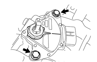
| *a | Neutral Basic Line |
| *b | Indicator |
Align the indicator with the neutral basic line.
Hold the park/neutral position switch assembly in that position and tighten the 2 bolts.
- Torque:
- 5.4 N*m (55 kgf*cm, 48 in.*lbf)
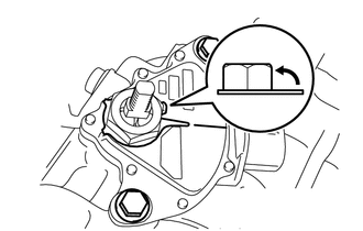
Using a screwdriver, stake the lock nut with the lock plate.
- NOTICE:
-
Be careful not to damage the park/neutral position switch assembly.
- HINT:
-
Tape the screwdriver tip before use.
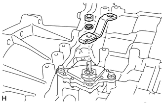
Install the transmission control shaft lever to the park/neutral position switch assembly with the nut and washer.
- Torque:
- 12.7 N*m (130 kgf*cm, 9 ft.*lbf)
35150B
50.INSTALL TRANSMISSION CASE PLUG ASSEMBLY
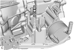
Coat a new O-ring with Toyota Genuine CVT fluid FE and install it to the transmission case plug assembly.
- NOTICE:
-
Ensure that the O-ring is not twisted.
Install the transmission case plug assembly to the continuously variable transaxle assembly.
- NOTICE:
-
Be careful not to damage the O-ring.
51.INSTALL BREATHER HOSE SUB-ASSEMBLY
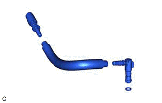
| *1 | No. 1 Breather Plug (CVT) |
| *2 | Breather Plug Hose |
| *3 | No. 2 Breather Plug (CVT) |
| *4 | O-ring |
Coat a new O-ring with Toyota Genuine CVT fluid FE and install it to the No. 2 breather plug (CVT).
- NOTICE:
-
Ensure that the O-ring is not twisted.
Install the No. 2 breather plug (CVT) to the breather plug hose.
Install the No. 1 breather plug (CVT) to the breather plug hose.
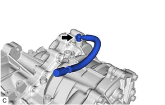
Install the transmission breather hose sub-assembly to the continuously variable transaxle assembly.
- NOTICE:
-
Be careful not to damage the O-ring.
35300C
52.INSTALL OIL PUMP WITH MOTOR ASSEMBLY
Apply Toyota Genuine CVT fluid FE to 2 new O-rings, and install them to the oil pump with motor assembly.
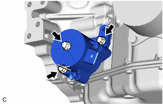
Temporarily install the oil pump with motor assembly to the continuously variable transaxle assembly with the 3 bolts.
- NOTICE:
- ·
Make sure that the O-ring is installed to the oil pump with motor assembly.
·Make sure that the O-ring is not moved out of place when installing the oil pump with motor assembly.
·To prevent the O-ring from being damaged, do not move the oil pump with motor assembly laterally with it contacting the continuously variable transaxle assembly.
Tighten the 3 bolts to install the oil pump with motor assembly.
- Torque:
- 22 N*m (224 kgf*cm, 16 ft.*lbf)
43420H
53.INSTALL FRONT DRIVE SHAFT OIL SEAL LH
43410M
54.INSTALL FRONT DRIVE SHAFT OIL SEAL RH
30400E
55.INSTALL CVT OIL PUMP TYPE T OIL SEAL
Ensure that there is no dirt or foreign matter on your hands and then apply MP grease to the entire periphery of the lip of a new CVT oil pump type T oil seal.
Temporarily install the CVT oil pump type T oil seal by pressing it to the installation surface of the oil pump housing by hand.
- NOTICE:
-
Be sure to install the CVT oil pump type T oil seal in the correct direction.
Clean the CVT oil pump type T oil seal contact surface of SST and the area around it.
- SST
- 09309-36010
| *a | Depth |
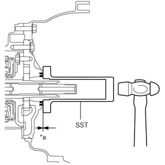
Using SST and a hammer, drive the CVT oil pump type T oil seal in evenly, until it is even with the side surface of the oil pump housing.
- Standard Depth:
0 to 0.5 mm (0 to 0.0197 in.)
- NOTICE:
- ·
Drive the CVT oil pump type T oil seal in gradually, while visually checking that it is even.
·After installation, confirm that the CVT oil pump type T oil seal has been driven in until it is even with the side surface of the oil pump housing.
·Wipe any extra grease off with your hand.