K313 CVT CONTINUOUSLY VARIABLE TRANSAXLE UNIT DISASSEMBLY
CAUTION / NOTICE / HINT
- NOTICE:
- ·
Clean the work area, tools to be used, other equipment, etc., thoroughly before performing this procedure, as there is a possibility that a CVT malfunction, which may prevent the vehicle from being driven, may occur if dust or fine foreign matter enters the CVT.
·Do not use cotton work gloves, cloths, paper towels, etc., that may produce lint, dust or foreign matter.
·When cleaning parts, make sure that dust or foreign matter does not enter the CVT.
·When replacing any tapered roller bearing (inner race) or tapered roller bearing (outer race), replace both the tapered roller bearing (inner race) and tapered roller bearing (outer race) with new ones.
·When the tapered roller bearing (inner race) is removed, the tapered roller bearing (inner race) and tapered roller bearing (outer race) need to be replaced.
·When the tapered roller bearing (inner race) is not removed, the tapered roller bearing (inner race) and tapered roller bearing (outer race) can be reused.
PROCEDURE

 30400E
1.REMOVE CVT OIL PUMP TYPE T OIL SEAL
30400E
1.REMOVE CVT OIL PUMP TYPE T OIL SEAL
- NOTICE:
- ·
Do not remove the front oil pump assembly from the CVT main body, as there is a possibility of the entry of dust and foreign matter.
·Clean the work area, the tools to be used, and other equipment, etc. thoroughly before the operation, as there is the possibility that a CVT malfunction, which could prevent the vehicle from being able to be driven, could occur if dust or fine foreign matter enters the CVT.
·Do not use cotton work gloves, cloths, or paper towels, etc. that may produce lint, dust or foreign matter.
·Perform the operation as quickly as possible, as dust and foreign matter could enter the CVT while the torque converter assembly is removed.
·Do not use an air gun until the torque converter assembly has been installed, as it could cause dust and foreign matter to be stirred up.
Clean the tips of both the claws of SST and the center bolt.
- SST
- 09308-10010
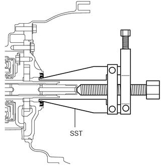
Using SST, remove the CVT oil pump type T oil seal.
- NOTICE:
-
Pay attention to the angle of the claws when opening them, and ensure that they do not come into contact with the oil pump housing, as there is the possibility that metal particles could be produced if they do.
43420H
2.REMOVE FRONT DRIVE SHAFT OIL SEAL LH
43410M
3.REMOVE FRONT DRIVE SHAFT OIL SEAL RH
35300C
4.REMOVE OIL PUMP WITH MOTOR ASSEMBLY
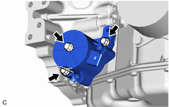
Remove the 3 bolts and oil pump with motor assembly from the continuously variable transaxle assembly.
Remove the 2 O-rings from the oil pump with motor assembly.
5.REMOVE BREATHER HOSE SUB-ASSEMBLY
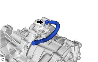
Using a screwdriver, remove the transmission breather hose sub-assembly from the continuously variable transaxle assembly.
- NOTICE:
-
Be careful not to damage the continuously variable transaxle assembly.
- HINT:
-
Tape the screwdriver tip before use.
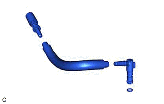
| *1 | No. 1 Breather Plug (CVT) |
| *2 | Breather Plug Hose |
| *3 | No. 2 Breather Plug (CVT) |
| *4 | O-ring |
Remove the No. 1 breather plug (CVT) from the breather plug hose.
Remove the No. 2 breather plug (CVT) from the breather plug hose.
Remove the O-ring from the No. 2 breather plug (CVT).
35150B
6.REMOVE TRANSMISSION CASE PLUG ASSEMBLY
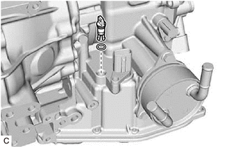
Remove the transmission case plug assembly from the continuously variable transaxle assembly.
Remove the O-ring from the transmission case plug assembly.
84540
7.REMOVE PARK/NEUTRAL POSITION SWITCH ASSEMBLY
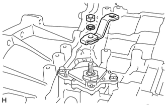
Remove the nut, washer and transmission control shaft lever from the park/neutral position switch assembly.
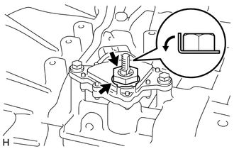
Pry out the lock plate and remove the lock nut and lock plate from the park/neutral position switch assembly.
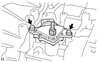
Remove the 2 bolts and park/neutral position switch assembly from the continuously variable transaxle assembly.
89413P
8.REMOVE TRANSMISSION REVOLUTION SENSOR (NIN)
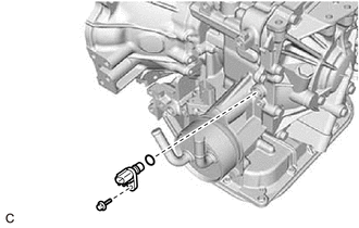
Remove the bolt and transmission revolution sensor (NIN) from the continuously variable transaxle assembly.
Remove the O-ring from the transmission revolution sensor (NIN).
89413M
9.REMOVE TRANSMISSION REVOLUTION SENSOR (NOUT)
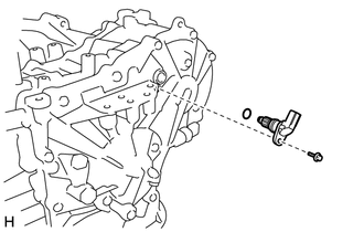
Remove the bolt and transmission revolution sensor (NOUT) from the continuously variable transaxle assembly.
Remove the O-ring from the transmission revolution sensor (NOUT).
89637K
10.REMOVE OIL PRESSURE SENSOR
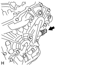
Using a 27 mm deep socket wrench, remove the oil pressure sensor from the continuously variable transaxle assembly.
33493C
11.REMOVE TRANSMISSION OIL COOLER
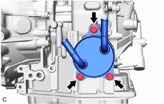
Remove the 3 bolts and transmission oil cooler from the continuously variable transaxle assembly.
Remove the 2 O-rings from the transmission oil cooler.
12.REMOVE TRANSAXLE HOUSING PLUG
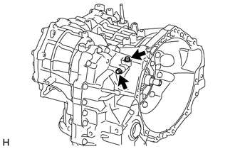
Remove the 2 transaxle housing plugs from the continuously variable transaxle assembly.
Remove the 2 O-rings from the 2 transaxle housing plugs.
13.REMOVE NO. 1 TRANSAXLE CASE PLUG
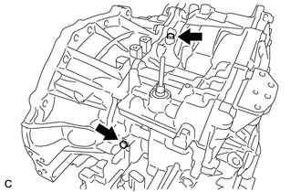
Remove the 2 No. 1 transaxle case plugs from the continuously variable transaxle assembly.
Remove the 2 O-rings from the 2 No. 1 transaxle case plugs.
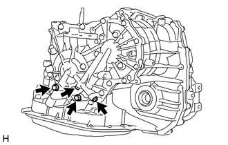
Remove the 4 No. 1 transaxle case plugs from the continuously variable transaxle assembly.
Remove the 4 O-rings from the 4 No. 1 transaxle case plugs.
14.REMOVE STRAIGHT SCREW PLUG
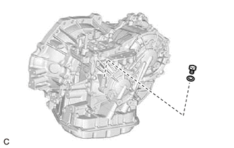
Remove the straight screw plug and gasket from the continuously variable transaxle assembly.
15.REMOVE REFILL PLUG
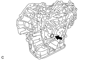
Remove the refill plug and gasket from the continuously variable transaxle assembly.
30400
16.SUPPORT CONTINUOUSLY VARIABLE TRANSAXLE ASSEMBLY
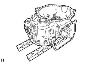
| *a | Wooden Block |
Place the continuously variable transaxle assembly on wooden blocks.
35106L
17.REMOVE TRANSAXLE OIL (CVT) PAN SUB-ASSEMBLY
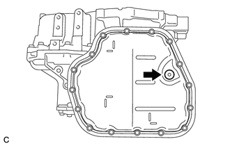
Using a 6 mm hexagon socket wrench, remove the overflow plug and gasket from the transaxle oil (CVT) pan sub-assembly.
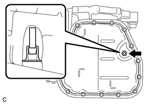
Using a 6 mm hexagon socket wrench, remove the overflow (CVT) tube from the transaxle oil (CVT) pan sub-assembly.
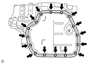
Remove the 16 bolts, transaxle oil (CVT) pan sub-assembly and transaxle oil pan (CVT) gasket from the continuously variable transaxle assembly.
- NOTICE:
-
Some fluid will remain in the transaxle oil (CVT) pan sub-assembly. Remove all the bolts, and carefully remove the transaxle oil (CVT) pan sub-assembly.
35394D
18.REMOVE OIL CLEANER (CVT) MAGNET
35330D
19.REMOVE OIL STRAINER ASSEMBLY
35410J
20.REMOVE TRANSMISSION VALVE BODY ASSEMBLY
82125M
21.REMOVE TRANSMISSION WIRE
89413N
22.REMOVE TRANSMISSION REVOLUTION SENSOR (NT)
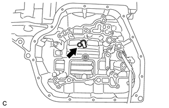
Remove the bolt and transmission revolution sensor (NT) from the continuously variable transaxle assembly.
35145D
23.REMOVE TRANSAXLE CASE GASKET
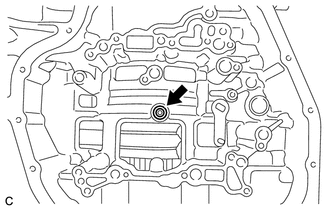
Remove the transaxle case gasket from the continuously variable transaxle assembly.
35111C
24.REMOVE TRANSAXLE HOUSING
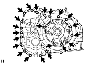
Remove the 22 bolts and transaxle housing from the transaxle case.
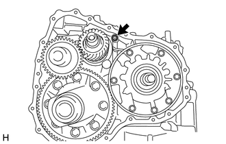
Remove the O-ring from the transaxle case.
35174B
25.REMOVE OIL RESERVOIR LOCK PLATE
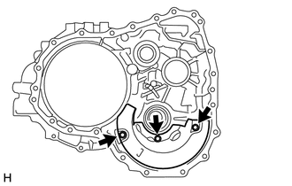
Remove the 3 bolts and oil reservoir lock plate from the transaxle housing.
35882E
26.REMOVE NO. 1 DIFFERENTIAL GEAR LUBE APPLY TUBE
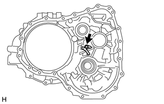
Remove the bolt.
Remove the No. 1 transaxle apply tube clamp from the No. 1 differential gear lube apply tube.
Remove the No. 1 differential gear lube apply tube from the transaxle housing.
41311E
27.REMOVE FRONT DIFFERENTIAL CASE FRONT TAPERED ROLLER BEARING (OUTER RACE)
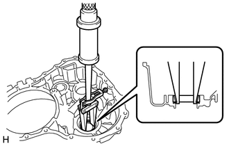
Using SST, remove the front differential case front tapered roller bearing (outer race) and shim from the transaxle housing.
- SST
- 09308-00010
41211A
28.REMOVE FRONT DRIVE PINION FRONT TAPERED ROLLER BEARING (OUTER RACE)
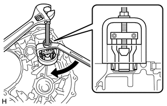
| *a | Turn |
| *b | Hold |
Using SST, remove the front drive pinion front tapered roller bearing (outer race) and shim from the transaxle housing.
- SST
- 09612-65014 (09612-01040)
35310A
29.REMOVE FRONT OIL PUMP ASSEMBLY
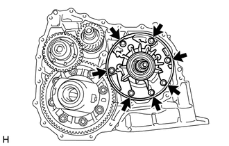
Remove the 7 bolts and front oil pump assembly from the transaxle case.
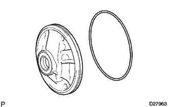
Remove the O-ring from the front oil pump assembly.
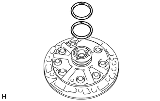
Remove the 2 oil seal rings from the front oil pump assembly.
35759A
30.REMOVE REDUCTION DRIVEN GEAR
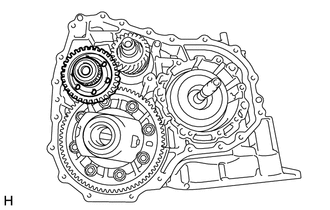
Remove the reduction driven gear from the transaxle case.
41211A
31.REMOVE FRONT DRIVE PINION FRONT TAPERED ROLLER BEARING (INNER RACE)
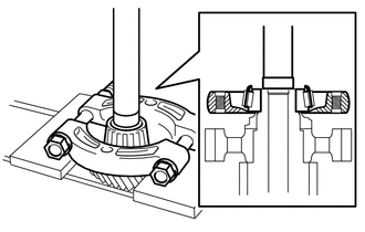
Using SST and a press, remove the front drive pinion front tapered roller bearing (inner race) from the reduction driven gear.
- SST
- 09950-00020
09950-60011 (09951-00240)
09950-70010 (09951-07100)
- NOTICE:
-
Be careful not to drop the reduction driven gear.
41211B
32.REMOVE FRONT DRIVE PINION REAR TAPERED ROLLER BEARING (INNER RACE)
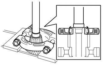
Using SST and a press, remove the front drive pinion rear tapered roller bearing (inner race) from the reduction driven gear.
- SST
- 09950-00020
09950-60011 (09951-00280)
09950-70010 (09951-07100)
- NOTICE:
-
Be careful not to drop the reduction driven gear.
41302F
33.REMOVE FRONT DIFFERENTIAL CASE SUB-ASSEMBLY
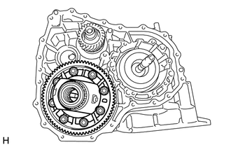
Remove the front differential case sub-assembly from the transaxle case.
41221
34.REMOVE FRONT DIFFERENTIAL RING GEAR
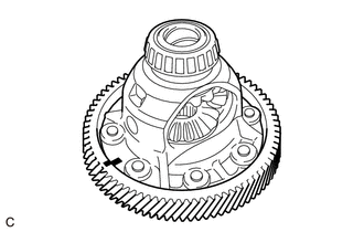
| *a | Matchmark |
Place matchmarks on the front differential ring gear and front differential case sub-assembly.
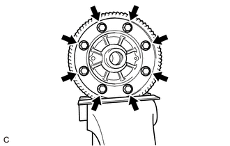
Secure the front differential ring gear in a vise between aluminum plates.
- NOTICE:
-
Do not overtighten the vise.
Remove the 8 bolts.
- NOTICE:
-
Be careful not to drop the front differential case sub-assembly.
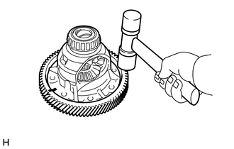
Using a plastic hammer, remove the front differential ring gear from the front differential case sub-assembly.
41311E
35.REMOVE FRONT DIFFERENTIAL CASE FRONT TAPERED ROLLER BEARING (INNER RACE)
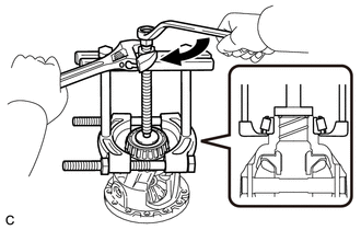
| *a | Turn |
| *b | Hold |
Using SST, remove the front differential case front tapered roller bearing (inner race) from the front differential case sub-assembly.
- SST
- 09950-00020
09950-00030
09950-40011 (09957-04010)
09950-60011 (09951-00390)
41311F
36.REMOVE FRONT DIFFERENTIAL CASE REAR TAPERED ROLLER BEARING (INNER RACE)
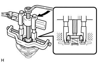
| *a | Turn |
| *b | Hold |
Using SST, remove the front differential case rear tapered roller bearing (inner race) from the front differential case sub-assembly.
- SST
- 09950-40011 (09951-04010, 09952-04010, 09953-04020, 09954-04010, 09955-04061, 09957-04010, 09958-04011)
09950-60011 (09951-00400)
35165B
37.REMOVE NO. 1 TRANSMISSION CASE PLATE
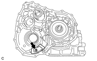
Remove the bolt and No. 1 transmission case plate from the transaxle case.
35882E
38.REMOVE NO. 2 DIFFERENTIAL GEAR LUBE APPLY TUBE

Remove the bolt.
Remove the No. 2 transaxle apply tube clamp from the No. 2 differential gear lube apply tube.
Remove the No. 2 differential gear lube apply tube from the transaxle case.
39.REMOVE INPUT SHAFT SUB-ASSEMBLY
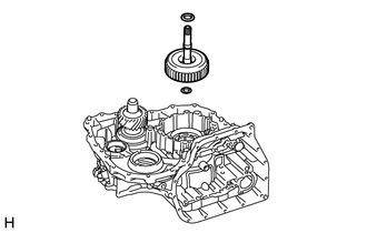
| *1 | Thrust Needle Roller Bearing |
| *2 | Thrust Bearing Race |
Remove the input shaft sub-assembly from the transaxle case.
Remove the thrust needle roller bearing and thrust bearing race.
35633H
40.INSPECT CLEARANCE OF FORWARD MULTIPLE DISC CLUTCH CLUTCH DISC
35633H
41.REMOVE FORWARD MULTIPLE DISC CLUTCH CLUTCH DISC
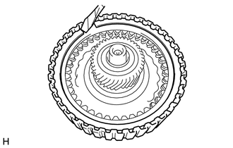
| *a | Protective Tape |
Using a screwdriver, remove the snap ring from the input shaft sub-assembly.
- NOTICE:
-
Be careful not to damage the input shaft sub-assembly.
- HINT:
-
Tape the screwdriver tip before use.

| *1 | Forward Clutch Flange |
| *2 | Forward Multiple Disc Clutch Clutch Disc |
| *3 | Forward Multiple Disc Clutch Clutch Plate |
| *4 | Clutch Cushion Plate |
Remove the forward clutch flange, 3 forward multiple disc clutch clutch discs, 3 forward multiple disc clutch clutch plates and clutch cushion plate from the input shaft sub-assembly.
35612D
42.REMOVE FORWARD CLUTCH PISTON
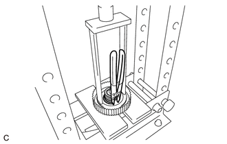
Place SST on the No. 1 clutch balancer and compress the forward clutch return spring sub-assembly with a press.
- SST
- 09387-00020
- NOTICE:
-
Stop the press when the No. 1 clutch balancer is lowered to 1 to 2 mm (0.0394 to 0.0787 in.) from the snap ring groove to prevent the No. 1 clutch balancer from being deformed.
Using a snap ring expander, remove the snap ring.
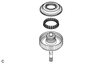
Remove the No. 1 clutch balancer and forward clutch return spring sub-assembly from the input shaft sub-assembly.
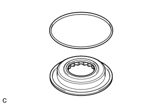
Remove the O-ring from the No. 1 clutch balancer.
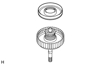
Using needle-nose pliers, remove the forward clutch piston from the input shaft sub-assembly.
- NOTICE:
-
Be careful not to damage the forward clutch piston and input shaft sub-assembly.
- HINT:
-
Tape the needle-nose pliers tips before use.
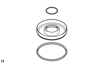
Remove the 2 O-rings from the forward clutch piston.
35720M
43.REMOVE PLANETARY GEAR ASSEMBLY
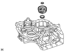
Remove the planetary gear assembly from the transaxle case.
Remove the 2 thrust needle roller bearings.
35075D
44.REMOVE FRONT PLANETARY RING GEAR SUB-ASSEMBLY
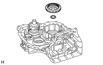
Remove the front planetary ring gear sub-assembly from the transaxle case.
Remove the thrust washer.
35681B
45.INSPECT CLEARANCE OF NO. 1 BRAKE DISC
35681B
46.REMOVE NO. 1 BRAKE DISC
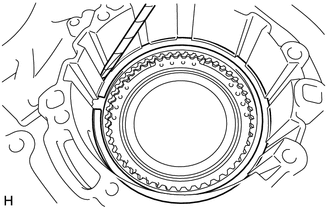
| *a | Protective Tape |
Using a screwdriver, remove the snap ring.
- NOTICE:
-
Be careful not to damage the transaxle case.
- HINT:
-
Tape the screwdriver tip before use.
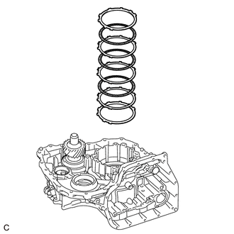
| *1 | Brake Flange |
| *2 | No. 1 Brake Disc |
| *3 | No. 1 Brake Plate |
| *4 | Brake Cushion Plate |
Remove the brake flange, 3 No. 1 brake discs, 3 No. 1 brake plates and brake cushion plate from the transaxle case.
35623L
47.REMOVE REVERSE BRAKE PISTON
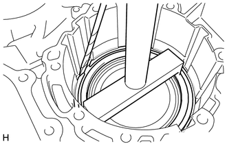
| *a | Protective Tape |
Place SST on the 1st and reverse brake return spring sub-assembly and compress the 1st and reverse brake return spring sub-assembly with a press.
- SST
- 09350-36010 (09350-06030)
09950-70010 (09951-07100)
- NOTICE:
-
Stop the press when the 1st and reverse brake return spring sub-assembly is lowered to 1 to 2 mm (0.0394 to 0.0787 in.) from the snap ring groove to prevent the 1st and reverse brake return spring sub-assembly from being deformed.
Using a screwdriver, remove the snap ring from the transaxle case.
- NOTICE:
-
Be careful not to damage the transaxle case.
- HINT:
-
Tape the screwdriver tip before use.
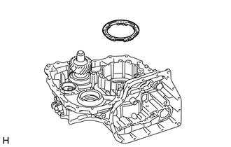
Remove the 1st and reverse brake return spring sub-assembly from the transaxle case.
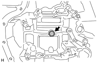
Hold the reverse brake piston and apply compressed air (392 kPa, 4.0 kgf/cm2, 57 psi) to the transaxle case to remove the reverse brake piston.
- HINT:
-
If the reverse brake piston does not pop out with compressed air, remove it with needle-nose pliers.
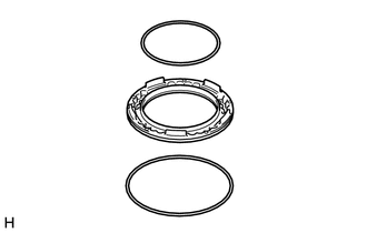
Remove the 2 O-rings from the reverse brake piston.
41311F
48.REMOVE FRONT DIFFERENTIAL CASE REAR TAPERED ROLLER BEARING (OUTER RACE)
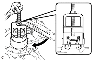
| *a | Turn |
| *b | Hold |
Using SST, remove the front differential case rear tapered roller bearing (outer race) from the transaxle case.
- SST
- 09612-65014 (09612-01020)
09527-17011
41211B
49.REMOVE FRONT DRIVE PINION REAR TAPERED ROLLER BEARING (OUTER RACE)
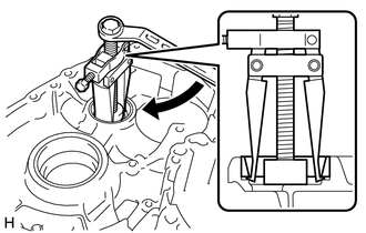
Using SST, remove the front drive pinion rear tapered roller bearing (outer race) from the transaxle case.
- SST
- 09308-10010
09950-60011 (09951-00300)
09950-40011 (09957-04010)