NR Series ENGINE MECHANICAL CYLINDER BLOCK INSPECTION
PROCEDURE

 1.INSPECT CONNECTING ROD THRUST CLEARANCE
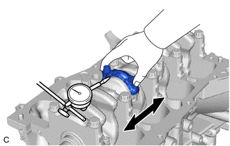
Using a dial indicator, measure the thrust clearance while moving the connecting rod back and forth.
- Standard Thrust Clearance:
0.1 to 0.5 mm (0.00394 to 0.0197 in.)
- Maximum Thrust Clearance:
0.5 mm (0.0197 in.)
- HINT:
-
If the thrust clearance is more than the maximum, replace the connecting rod. If necessary, replace the crankshaft.
2.INSPECT CONNECTING ROD OIL CLEARANCE
- HINT:
-
Using SST, install and alternately tighten the 2 connecting rod bolts in several steps.
Remove the connecting rod bearing cap and lower connecting rod bearing.
Clean the crankshaft crank pin and upper connecting rod bearing.
Check the crankshaft crank pin and upper connecting rod bearing for pitting and scratches.
- HINT:
-
If the crank pin or upper connecting rod bearing is damaged, replace the connecting rod bearings. If necessary, replace the crankshaft.
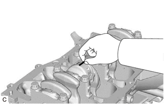
| *a | Plastigage |
Lay a strip of Plastigage on the crank pin.
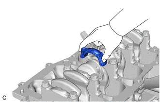
| *a | Front Mark |
Check that the front mark of the connecting rod bearing cap is facing the correct direction, and install the connecting rod bearing cap to the connecting rod.
Apply a light coat of engine oil to the threads and under the heads of the 2 connecting rod bolts.
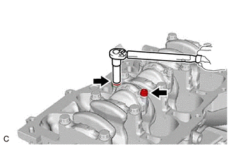
Using SST, install and alternately tighten the 2 connecting rod bolts in several steps.
- SST
- 09205-16011
- Torque:
- 15 N*m (153 kgf*cm, 11 ft.*lbf)
| *a | Paint Mark |
| *b | 90° |

|
Front of Engine |
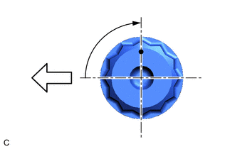
Mark the front of each connecting rod bolt with paint.
Tighten the connecting rod bolts 90° as shown in the illustration.
- NOTICE:
-
Do not turn the crankshaft during the measurement.
Remove the 2 connecting rod bolts and connecting rod bearing cap.
| *a | Plastigage |
| *b | Number Mark |
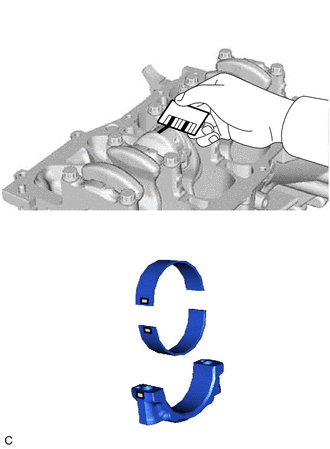
Measure the Plastigage at its widest point.
- Standard Oil Clearance:
0.010 to 0.036 mm (0.000394 to 0.00142 in.)
- Maximum Oil Clearance:
0.036 mm (0.00142 in.)
- HINT:
- ·
If the oil clearance is more than the maximum, replace the connecting rod bearings. If necessary, replace the crankshaft.
·If replacing a connecting rod bearing, select a new one with the same number as marked on the connecting rod bearing cap. There are 3 sizes of standard connecting rod bearings, marked "1", "2", or "3" accordingly.
- Standard Connecting Rod Big End Inside Diameter:
Mark Specified Condition 1 45.000 to 45.008 mm (1.77165 to 1.77196 in.) 2 45.009 to 45.016 mm (1.77200 to 1.77228 in.) 3 45.017 to 45.024 mm (1.77232 to 1.77259 in.)
- Standard Connecting Rod Bearing Center Wall Thickness:
Mark Specified Condition 1 1.492 to 1.495 mm (0.0587 to 0.0589 in.) 2 1.496 to 1.498 mm (0.0589 to 0.0590 in.) 3 1.499 to 1.501 mm (0.0590 to 0.0591 in.)
- Standard Crankshaft Pin Diameter:
Mark Specified Condition 1, 2, 3 41.992 to 42.000 mm (1.65323 to 1.65354 in.)
- NOTICE:
-
Completely remove the Plastigage after the measurement.
3.INSPECT CRANKSHAFT THRUST CLEARANCE
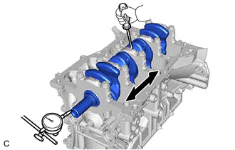
Using a dial indicator, measure the crankshaft thrust clearance while prying the crankshaft back and forth with a screwdriver.
- Standard Thrust Clearance:
0.04 to 0.24 mm (0.00157 to 0.00945 in.)
- Maximum Thrust Clearance:
0.24 mm (0.00945 in.)
- HINT:
-
If the thrust clearance is more than the maximum, replace the crankshaft thrust washer set. If necessary, replace the crankshaft.
- Standard Thrust Washer Thickness:
1.93 to 1.98 mm (0.0760 to 0.0780 in.)
4.INSPECT CRANKSHAFT OIL CLEARANCE
Check the crankshaft journals and crankshaft bearings for pitting and scratches.
Install the crankshaft bearings.
Install the upper crankshaft thrust washers.
Clean each main journal and crankshaft bearing.
Place the crankshaft on the cylinder block sub-assembly.
| *a | Plastigage |
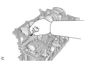
Lay a strip of Plastigage across each journal.
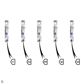
| *a | Front Mark and Number |
Confirm the front marks and numbers, and place the 5 No. 1 crankshaft bearing caps on the cylinder block sub-assembly.
- HINT:
-
A number is marked on each No. 1 crankshaft bearing cap to indicate its installation position.
Install the No. 1 crankshaft bearing caps.
- NOTICE:
-
Do not turn the crankshaft.
Remove the No. 1 crankshaft bearing caps.
Measure the Plastigage at its widest point.
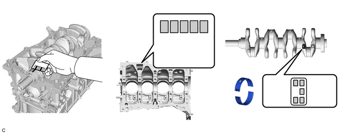
| *a | Plastigage | *b | Cylinder Block Number Mark (A) |
| *c | Crankshaft Number Mark (B) | *d | Diameter Mark |
- Standard Oil Clearance:
0.012 to 0.028 mm (0.000472 to 0.00110 in.)
- Maximum Oil Clearance:
0.028 mm (0.00110 in.)
- NOTICE:
-
Completely remove the Plastigage after the measurement.
- HINT:
-
If the oil clearance is more than the maximum, replace the crankshaft bearings. If necessary, replace the crankshaft.
If replacing a crankshaft bearing, select a new one with the same number.
- HINT:
- ·
If the number of the crankshaft bearing cannot be determined, calculate the correct crankshaft bearing number by adding together the numbers imprinted on the cylinder block sub-assembly and crankshaft. Then select a new crankshaft bearing with the calculated number according to the chart below. There are 4 sizes of standard crankshaft bearings, marked "1", "2", "3" or "4" accordingly.
·Example: Cylinder block "3" + Crankshaft "5" = Total number 8 (Use crankshaft bearing "3")
- Crankshaft Bearing:
Cylinder block sub-assembly + Crankshaft Crankshaft bearing to be used 0 to 2 "1" 3 to 5 "2" 6 to 8 "3" 9 to 11 "4"
- Standard Cylinder Block Journal Bore Diameter:
Mark Specified Condition 0 52.000 to 52.002 mm (2.04724 to 2.04732 in.) 1 52.003 to 52.004 mm (2.04736 to 2.04740 in.) 2 52.005 to 52.006 mm (2.04744 to 2.04748 in.) 3 52.007 to 52.009 mm (2.04752 to 2.04759 in.) 4 52.010 to 52.011 mm (2.04763 to 2.04767 in.) 5 52.012 to 52.013 mm (2.04771 to 2.04775 in.) 6 52.014 to 52.016 mm (2.04779 to 2.04787 in.)
- Standard Crankshaft Journal Diameter:
Mark Specified Condition 0 47.999 to 48.000 mm (1.88972 to 1.88976 in.) 1 47.997 to 47.998 mm (1.88964 to 1.88968 in.) 2 47.995 to 47.996 mm (1.88956 to 1.88960 in.) 3 47.993 to 47.994 mm (1.88948 to 1.88952 in.) 4 47.991 to 47.992 mm (1.88941 to 1.88945 in.) 5 47.988 to 47.990 mm (1.88929 to 1.88937 in.)
- Standard Bearing Center Wall Thickness:
Mark Specified Condition 1 1.991 to 1.994 mm (0.07839 to 0.07850 in.) 2 1.995 to 1.997 mm (0.07854 to 0.07862 in.) 3 1.998 to 2.000 mm (0.07866 to 0.07874 in.) 4 2.001 to 2.003 mm (0.07878 to 0.07886 in.)
5.INSPECT CYLINDER BLOCK SUB-ASSEMBLY FOR WARPAGE
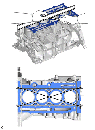
Using a precision straightedge and feeler gauge, check the surfaces which contact the cylinder head gasket for warpage.
- Maximum Warpage:
0.05 mm (0.00197 in.)
- HINT:
-
If the warpage is more than the maximum, replace the cylinder block sub-assembly.
6.INSPECT CYLINDER BORE
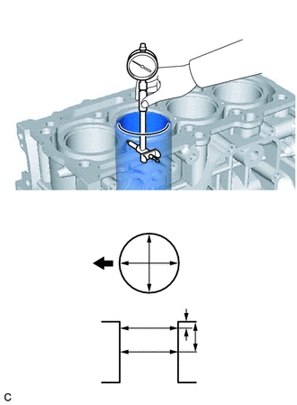
| *a | Thrust Direction |
| *b | Axial Direction |
| *c | 10 mm |
| *d | 60 mm |

|
Front of Engine |
Using a cylinder gauge, measure the cylinder bore diameter at the positions (A) and (B) in the thrust and axial directions.
- Reference Diameter (New Parts):
71.500 to 71.513 mm (2.81496 to 2.81547 in.)
- Maximum Diameter:
71.63 mm (2.82007 in.)
- Measurement Position:
Measurement Position Cylinder Bore Position A 10 mm (0.394 in.) from top edge B 60 mm (2.36 in.) from top edge
- HINT:
-
If the average diameter of 4 positions is more than the maximum, replace the cylinder block sub-assembly.
15708
7.INSPECT NO. 1 OIL NOZZLE SUB-ASSEMBLY
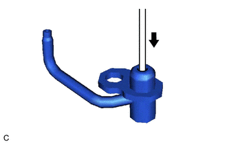
| *a | Pin |
Push the check valve with a pin to check that it is not stuck.
- HINT:
-
If the check valve is stuck, replace the No. 1 oil nozzle sub-assembly.
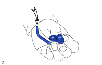
Apply air into (A). Check that air does not leak through (B).
- HINT:
-
If air leaks, clean or replace the No. 1 oil nozzle sub-assembly.
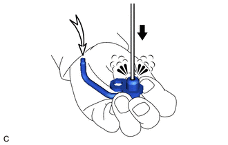
| *a | Pin |
Push the check valve with a pin while applying air into (A). Check that air passes through (B).
- HINT:
-
If air does not pass through (B), clean or replace the No. 1 oil nozzle sub-assembly.
8.INSPECT PISTON SUB-ASSEMBLY WITH CONNECTING ROD
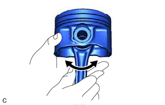
Check the fitting condition between the piston and piston pin by trying to move the piston back and forth on the piston pin.
- HINT:
-
If abnormal movement is felt, replace the piston and piston pin as a set.
13101
9.INSPECT PISTON
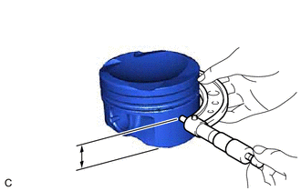
| *a | 9.7 mm |
Using a micrometer, measure the piston diameter at a position 9.7 mm (0.382 in.) from the bottom of the piston (refer to the illustration).
- Reference Piston Diameter (New Parts):
71.482 to 71.514 mm (2.81 to 2.82 in.)
- HINT:
-
If the piston diameter is less than the minimum, replace the piston and piston pin as a set.
10.INSPECT PISTON OIL CLEARANCE
Subtract the piston diameter measurement from the cylinder bore diameter measurement.
- Reference Oil Clearance (New Parts):
-0.006 to 0.037 mm (-0.000236 to 0.00146 in.)
- Maximum Oil Clearance:
0.08 mm (0.00315 in.)
- HINT:
-
If the piston oil clearance is more than the maximum, replace all the pistons with piston pins. If necessary, replace the cylinder block sub-assembly.
11.INSPECT RING GROOVE CLEARANCE
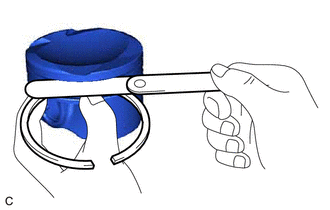
Using a feeler gauge, measure the clearance between a new piston ring set and the wall of the ring groove.
- Standard Ring Groove Clearance:
Item Specified Condition No. 1 Compression Ring 0.02 to 0.06 mm (0.000787 to 0.00236 in.) No. 2 Compression Ring 0.02 to 0.06 mm (0.000787 to 0.00236 in.) Oil Ring 0.07 to 0.13 mm (0.00276 to 0.00512 in.)
- HINT:
-
If the groove clearance is not as specified, replace the piston and piston pin as a set.
12.INSPECT PISTON RING END GAP
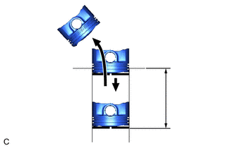
| *a | 50 mm |
Using a piston, push the piston ring a little beyond the bottom of the ring travel, 50 mm (1.97 in.) from the top of the cylinder block sub-assembly.

Using a feeler gauge, measure the end gap.
- Standard End Gap:
Item Specified Condition No. 1 Compression Ring 0.18 to 0.22 mm (0.00709 to 0.00866 in.) No. 2 Compression Ring 0.50 to 0.60 mm (0.0197 to 0.0236 in.) Oil Ring 0.10 to 0.35 mm (0.00394 to 0.0138 in.)
- Maximum End Gap:
Item Specified Condition No. 1 Compression Ring 0.43 mm (0.0169 in.) No. 2 Compression Ring 0.80 mm (0.0315 in.) Oil Ring 0.55 mm (0.0217 in.)
- HINT:
-
If the end gap is more than the maximum, replace the piston ring. If the end gap is more than the maximum even with a new piston ring, replace the cylinder block sub-assembly.
13.INSPECT PISTON PIN OIL CLEARANCE
- HINT:
-
When replacing the piston sub-assembly with pin with a supply part, there are a number of piston diameter sizes to choose from, but there is only one size of piston pin diameter.
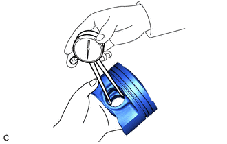
Using a caliper gauge, measure the piston pin bore diameter.
- Standard Piston Pin Bore Diameter:
Item Specified Condition Mark A 20.006 to 20.009 mm (0.78764 to 0.78775 in.) Mark B 20.010 to 20.012 mm (0.78779 to 0.78787 in.) Mark C 20.013 to 20.015 mm (0.78791 to 0.78799 in.)
- HINT:
-
If the diameter is not as specified, replace the piston and piston pin as a set.
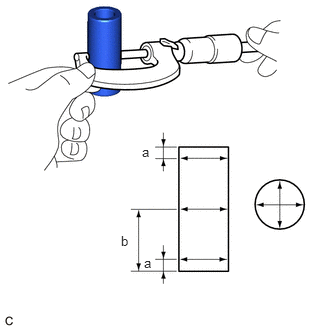
Using a micrometer, measure the piston pin diameter.
- Standard Piston Pin Diameter:
20.004 to 20.013 mm (0.78756 to 0.78791 in.)
Item Specified Condition Mark A 20.004 to 20.007 mm (0.78756 to 0.78768 in.) Mark B 20.008 to 20.010 mm (0.78771 to 0.78779 in.) Mark C 20.011 to 20.013 mm (0.78783 to 0.78791 in.)
- HINT:
-
If the diameter is not as specified, replace the piston and piston pin as a set.
- Measurement Position:
Measurement Position Piston Pin Position a 5 mm (0.197 in.) from side edge b 25 mm (0.984 in.) from side edge
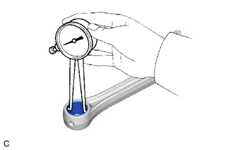
Using a caliper gauge, measure the connecting rod small end bush bore diameter.
- Standard Connecting Rod Small End Bush Bore Diameter:
20.012 to 20.021 mm (0.78787 to 0.78823 in.)
Item Specified Condition Mark A 20.012 to 20.015 mm (0.78787 to 0.78799 in.) Mark B 20.016 to 20.018 mm (0.78803 to 0.78811 in.) Mark C 20.019 to 20.021 mm (0.78815 to 0.78823 in.)
- HINT:
-
If the diameter is not as specified, replace the connecting rod small end bush.
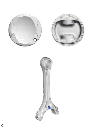
| *a | Front Mark |
| *b | Piston Pin Bore Diameter Mark |
| *c | Connecting Rod Small End Bush Bore Diameter Mark |
| *d | Top Side |
| *e | Bottom Side |
Subtract the piston pin diameter measurement from the piston pin bore diameter measurement.
- Standard Oil Clearance:
-0.001 to 0.005 mm (-0.0000394 to 0.000197 in.)
- Maximum Oil Clearance:
0.008 mm (0.00031 in.)
- HINT:
-
If the oil clearance is more than the maximum, replace the connecting rod. If necessary, replace the piston and piston pin as a set.
Subtract the piston pin diameter measurement from the bushing inside diameter measurement.
- Standard Oil Clearance:
-0.001 to 0.005 mm (-0.0000394 to 0.000197 in.)
- Maximum Oil Clearance:
0.08 mm (0.00315 in.)
- HINT:
-
If the oil clearance is more than the maximum, replace the connecting rod small end bush. If necessary, replace the piston and piston pin as a set.
14.INSPECT CONNECTING ROD BOLT
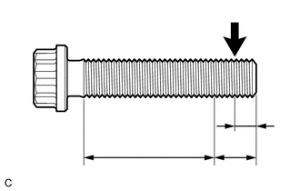
| *a | Measurement Area (B) |
| *b | 5.0 mm (0.197 in.) |
| *c | 10 mm (0.394 in.) |
|
|
Measurement Point (A) |
Using a vernier caliper, measure the diameter of the threads at the measurement point (A).
- Standard Diameter:
6.86 to 7.00 mm (0.270 to 0.276 in.)
- HINT:
-
If there is any thread deformation, replace the connecting rod bolt with a new one.
Using a vernier caliper, measure the diameter of the threads at several points within the measurement area (B) shown in the illustration.
- HINT:
- ·
Diameter measurements should be done at several points.
·If there is any thread deformation, replace the connecting rod bolt with a new one.
Calculate the difference between the measurement of (A) and the measurement of (B).
- Difference between (A) and (B):
0.15 mm (0.00591 in.) or less
- NOTICE:
-
If the difference between (A) and (B) is more than the maximum, replace the connecting rod bolt with a new one. Failure to do so may lead to engine damage.
- HINT:
-
If there is any thread deformation, replace the connecting rod bolt with a new one.
13411
15.INSPECT CRANKSHAFT
Inspect the runout.
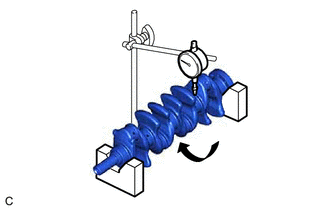
Using a dial indicator and V-blocks, measure the runout as shown in the illustration.
- Maximum Runout:
0.015 mm (0.000591 in.)
- HINT:
-
If the runout is more than the maximum, replace the crankshaft.
Inspect the main journals.
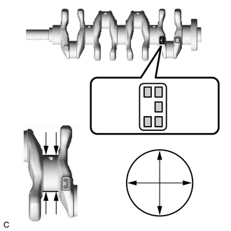
Using a micrometer, measure the diameter of each main journal.
- Standard Diameter:
47.988 to 48.000 mm (1.88929 to 1.88976 in.)
- HINT:
-
If the diameter is not as specified, check the crankshaft oil clearance.
Check each main journal for taper and out-of-round as shown in the illustration.
- Maximum Taper and Out-of-Round:
0.02 mm (0.000787 in.)
- HINT:
-
If the taper or out-of-round is more than the maximum, replace the crankshaft.
- Standard Diameter (Reference):
Mark Specified Condition 0 47.999 to 48.000 mm (1.88972 to 1.88976 in.) 1 47.997 to 47.998 mm (1.88964 to 1.88968 in.) 2 47.995 to 47.996 mm (1.88956 to 1.88960 in.) 3 47.993 to 47.994 mm (1.88948 to 1.88952 in.) 4 47.991 to 47.992 mm (1.88941 to 1.88945 in.) 5 47.988 to 47.990 mm (1.88929 to 1.88937 in.)
Inspect the crank pin.
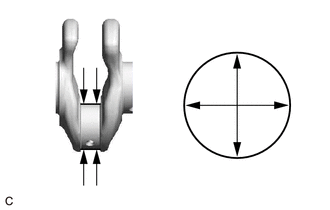
Using a micrometer, measure the diameter of each crank pin.
- Standard Diameter:
41.992 to 42.000 mm (1.65323 to 1.65354 in.)
- HINT:
-
If the diameter is not as specified, check the connecting rod oil clearance.
Inspect each crank pin for taper and out-of-round.
- Maximum Taper and Out-of-Round:
0.02 mm (0.000787 in.)
- HINT:
-
If the taper or out-of-round is more than the maximum, replace the crankshaft.
11416
16.INSPECT CRANKSHAFT BEARING CAP SET BOLT
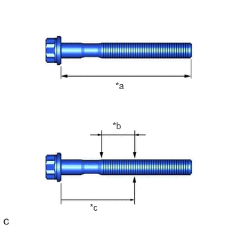
| *a | Measurement Length |
| *b | Measurement Area |
| *c | 55 mm (2.17 in.) |
Using a vernier caliper, measure the length of the crankshaft bearing cap set bolt from the seat to the end.
- Standard Length:
84.3 to 85.7 mm (3.32 to 3.37 in.)
- Maximum Length:
86.7 mm (3.41 in.)
- NOTICE:
- ·
If the length is greater than the maximum, replace the crankshaft bearing cap set bolt with a new one. Failure to do so may lead to engine damage.
·If there is any thread deformation, replace the crankshaft bearing cap set bolt with a new one.
Using a vernier caliper, measure the minimum diameter of the threads at several points within the area shown in the illustration.
- Standard Diameter:
9.77 to 9.96 mm (0.385 to 0.392 in.)
- Minimum Diameter:
9.1 mm (0.358 in.)
- NOTICE:
- ·
Diameter measurements should be done at several points.
·If the diameter is less than the minimum, replace the crankshaft bearing cap set bolt with a new one. Failure to do so may lead to engine damage.
·If there is any thread deformation, replace the crankshaft bearing cap set bolt with a new one.