NR Series ENGINE MECHANICAL ENGINE UNIT REASSEMBLY
CAUTION / NOTICE / HINT
- HINT:
-
Perform "Inspection After Repair" after replacing the camshaft, No. 2 camshaft, camshaft timing gear assembly or camshaft timing exhaust gear assembly.
PROCEDURE

 11151A
1.INSTALL CAMSHAFT BEARING CAP SETTING RING PIN
11151A
1.INSTALL CAMSHAFT BEARING CAP SETTING RING PIN
- HINT:
-
It is not necessary to remove the camshaft bearing cap setting ring pins unless they are being replaced.
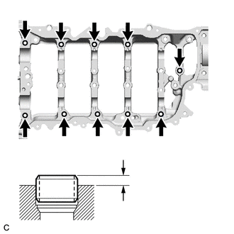
| *a | Camshaft Housing Sub-assembly Top Side |
| *b | Protrusion Height |
Using a plastic hammer, tap 10 new camshaft bearing cap setting ring pins into the camshaft housing sub-assembly.
- Standard Protrusion Height:
2.5 to 3.5 mm (0.0984 to 0.138 in.)
11420
2.INSTALL STIFFENING CRANKCASE ASSEMBLY
- NOTICE:
-
It is not necessary to remove ring pins unless they are being replaced.
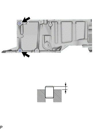
| *a | LH Side |
| *b | Protrusion Height |
Using a plastic hammer, tap 2 new ring pins into the stiffening crankcase assembly.
- Standard Protrusion Height:
3.5 to 4.5 mm (0.138 to 0.177 in.)
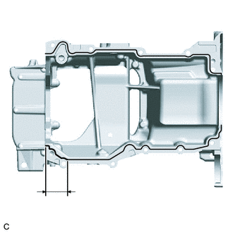
| *a | Seal Packing (2.0 to 3.0 mm (0.0787 to 0.118 in.)) |
| *b | Width: 6.0 to 8.0 mm (0.236 to 0.315 in.) Thickness: 2.5 to 3.5 mm (0.0984 to 0.138 in.) |
| *c | 47 mm (1.85 in.) |
Apply seal packing as shown in the illustration.
- Seal Packing:
Toyota Genuine Seal Packing Black, Three bond 1207B or equivalent
- NOTICE:
- ·
Remove any oil from the contact surfaces.
·Install the stiffening crankcase assembly within 3 minutes and tighten the bolts within 15 minutes of applying seal packing.
·Do not add engine oil for at least 2 hours after installing the stiffening crankcase assembly.
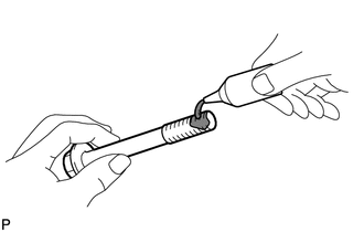
| *a | Adhesive |
Apply adhesive to 2 or 3 threads at the end of the bolt (A).
- Adhesive:
Toyota Genuine Adhesive 1324, Three bond 1324 or equivalent
- NOTICE:
-
Tighten the bolt within 3 minutes of applying adhesive.
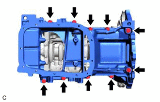
Install the stiffening crankcase assembly with the 10 bolts in the order shown in the illustration.
- Torque:
- 21 N*m (214 kgf*cm, 15 ft.*lbf)
Wipe off any excess seal packing with a clean piece of cloth.
11401L
3.INSTALL REAR ENGINE OIL SEAL
89439
4.INSTALL SENSOR BRACKET
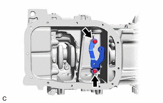
Install the sensor bracket to the stiffening crankcase assembly with the 2 bolts.
- Torque:
- 10 N*m (102 kgf*cm, 7 ft.*lbf)
89491
5.INSTALL ENGINE OIL LEVEL SENSOR
15100
6.INSTALL OIL PUMP ASSEMBLY
7.INSTALL STUD BOLT
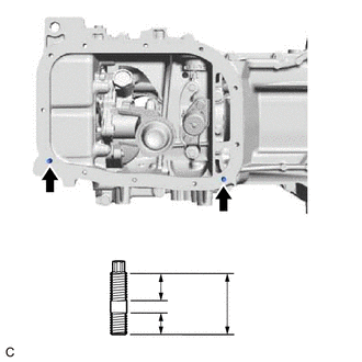
| *a | 9 mm (0.354 in.) |
| *b | 19 mm (0.748 in.) |
Using an E6 "TORX" socket wrench, install the 2 stud bolts to the stiffening crankcase assembly.
- Torque:
- 5.0 N*m (51 kgf*cm, 44 in.*lbf)
12102A
8.INSTALL NO. 2 OIL PAN SUB-ASSEMBLY
Remove any remaining seal packing.
- NOTICE:
- ·
Remove any oil from the contact surfaces.
·Install the No. 2 oil pan sub-assembly within 3 minutes and tighten the bolts within 10 minutes of applying seal packing.
·Do not add engine oil for at least 2 hours after installing the No. 2 oil pan sub-assembly.
·Do not drop any oil on the contact surfaces of the stiffening crankcase assembly or No. 2 oil pan sub-assembly.
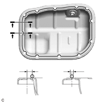
| *a | Seal Packing |
| *b | 6.0 mm (0.236 in.) |
| *c | 3.0 to 4.5 mm (0.118 to 0.177 in.) |
Apply seal packing in a continuous line as shown in the illustration.
- Seal Packing:
Toyota Genuine Seal Packing Black, Three Bond 1207B or equivalent
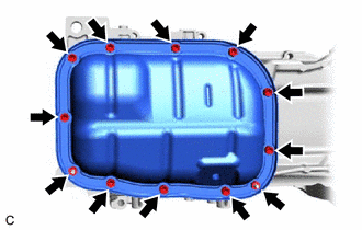
| *a | Nut |
Install the No. 2 oil pan sub-assembly with the 10 bolts and 2 nuts in several steps in the order shown in the illustration.
- Torque:
- 10 N*m (102 kgf*cm, 7 ft.*lbf)
12101A
9.INSTALL OIL PAN DRAIN PLUG
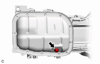
Install a new oil pan drain plug gasket and the oil pan drain plug to the No. 2 oil pan sub-assembly.
- Torque:
- 37 N*m (377 kgf*cm, 27 ft.*lbf)
11445
10.INSTALL CYLINDER BLOCK WATER JACKET SPACER

|
Front of Engine |
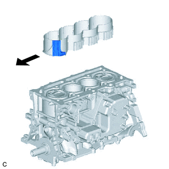
Install the cylinder block water jacket spacer to the cylinder block sub-assembly as shown in the illustration.
11115
11.INSTALL CYLINDER HEAD GASKET
11101
12.INSTALL CYLINDER HEAD SUB-ASSEMBLY
- HINT:
-
The cylinder head set bolts are tightened in 3 progressive steps.
Clean the cylinder block sub-assembly and cylinder head sub-assembly with solvent.
Place the cylinder head sub-assembly on the cylinder block sub-assembly.
- NOTICE:
- ·
Remove any oil from the contact surface of the cylinder head sub-assembly.
·Place the cylinder head sub-assembly on the cylinder block sub-assembly gently in order not to damage the cylinder head gasket with the bottom of the cylinder head sub-assembly.
Install the 10 cylinder head set plate washers to the 10 cylinder head set bolts.
Apply a light coat of engine oil to the threads and under the heads of the cylinder head set bolts.
Step 1:
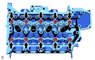
Using a 10 mm bi-hexagon socket wrench, install and uniformly tighten the 10 cylinder head set bolts in several steps in the order shown in the illustration.
- Torque:
- 32 N*m (326 kgf*cm, 24 ft.*lbf)
- NOTICE:
-
Do not drop the cylinder head set plate washers for the cylinder head set bolts into the cylinder head sub-assembly.
Step 2:
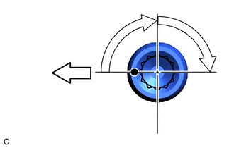
| *a | Paint Mark |
| *b | 90° |

|
Front of Engine |
Mark each cylinder head set bolt head with paint as shown in the illustration.
Tighten the cylinder head set bolts 90° in the order shown in step 1.
Step 3:
Tighten the cylinder head set bolts another 90° in the order shown in step 1.
Check that the paint marks are now at a 180° angle to the front.
- NOTICE:
-
Do not add engine oil for at least 2 hours after installing the cylinder head sub-assembly.
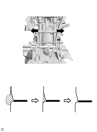
| *1 | Cylinder Head Sub-assembly |
| *2 | Cylinder Block Sub-assembly |
| *3 | Cylinder Head Gasket |
| *a | Direction to wipe off |
| *b | Before Wiping Off |
| *c | After Wiping Off |
| *d | After Wiping by Cloth |
| *e | Seal Packing |
| *f | Chamfer of Cylinder Head Sub-assembly |
| *g | Chamfer of Cylinder Block Sub-assembly |
After tightening the cylinder head set bolts, wipe off any seal packing that seeped out from the contact surfaces between the cylinder head sub-assembly and cylinder block sub-assembly.
- NOTICE:
- ·
Be sure to wipe off the seal packing from inside to outside, parallel to the joint line.
·Be sure to avoid clogging the bolt holes when wiping off the seal packing.
Using a cloth, wipe off any seal packing from the chamfers of the cylinder head sub-assembly and cylinder block sub-assembly.
- NOTICE:
- ·
Be sure to wipe off the seal packing from inside to outside, parallel to the joint line.
·Be sure to avoid clogging the bolt holes when wiping off the seal packing.
·Do not wipe off the seal packing to the extent that the end of the cylinder head gasket is exposed.
·Do not leave any seal packing on the chamfers of the cylinder block sub-assembly or cylinder head sub-assembly.
13716
13.INSTALL VALVE STEM CAP
Apply a light coat of engine oil to the valve stem ends.
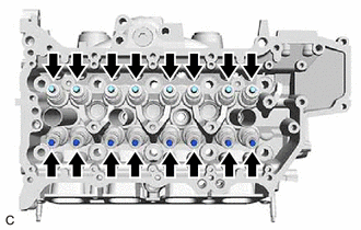
Install the 16 valve stem caps to the cylinder head sub-assembly.
- NOTICE:
- ·
Install the same parts to their original positions.
·Do not drop the valve stem caps into the cylinder head sub-assembly.
13750
14.INSTALL VALVE LASH ADJUSTER ASSEMBLY
Inspect the 16 valve lash adjuster assemblies before installing them.
Install the 16 valve lash adjuster assemblies to the cylinder head sub-assembly.
- NOTICE:
-
Install the same parts to their original positions.
13801
15.INSTALL NO. 1 VALVE ROCKER ARM SUB-ASSEMBLY
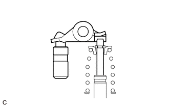
| *1 | Valve Lash Adjuster Assembly |
| *2 | No. 1 Valve Rocker Arm Sub-assembly |
| *3 | Valve Stem Cap |
Apply engine oil to the tips of the valve lash adjuster assemblies and valve stem caps.
Install the 16 No. 1 valve rocker arm sub-assemblies as shown in the illustration.
- NOTICE:
-
Install the same parts to their original positions.
11103
16.INSTALL CAMSHAFT HOUSING SUB-ASSEMBLY
15678A
17.INSTALL OIL CONTROL VALVE FILTER
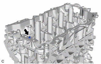
Install the oil control valve filter to the camshaft housing sub-assembly.
13512
18.INSTALL NO. 2 CAMSHAFT
13511
19.INSTALL CAMSHAFT
20.INSTALL CAMSHAFT BEARING CAP
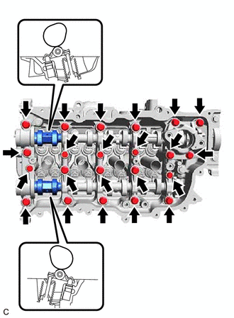
Set the camshaft and No. 2 camshaft as shown in the illustration.
Install the 5 camshaft bearing caps to the camshaft housing sub-assembly.
Install and uniformly tighten the 22 bolts in the order shown in the illustration.
- Torque:
- Bolt (A) : 16 N*m (163 kgf*cm, 12 ft.*lbf)
- except Bolt (A) : 28 N*m (286 kgf*cm, 21 ft.*lbf)
- NOTICE:
- ·
After installing the camshaft housing sub-assembly, make sure that the cam lobes are positioned as shown in the illustration.
·If any of the bolts are loosened during installation, remove the camshaft housing sub-assembly, clean the installation surfaces, and reapply seal packing.
·If the camshaft housing sub-assembly is removed because any of the bolts are loosened during installation, make sure that the previously applied seal packing does not enter any oil passages.
·After installing the camshaft housing sub-assembly, wipe off any seal packing that seeped out from between the camshaft housing sub-assembly and the cylinder head sub-assembly.
16341
21.INSTALL WATER OUTLET GASKET
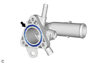
Install a new water outlet gasket to the water outlet.
22.INSTALL WATER OUTLET
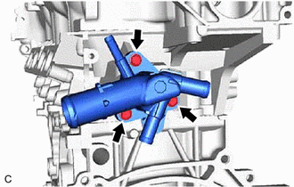
Install the water outlet to the cylinder head sub-assembly with the 3 bolts.
- Torque:
- 10 N*m (102 kgf*cm, 7 ft.*lbf)
89422A
23.INSTALL ENGINE COOLANT TEMPERATURE SENSOR
82125N
24.INSTALL NO. 5 ENGINE WIRE
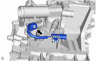
Engage the wire harness clamp and install the No. 5 engine wire to the water outlet.
Connect the engine coolant temperature sensor connector.
16295
25.INSTALL NO. 7 WATER BY-PASS HOSE
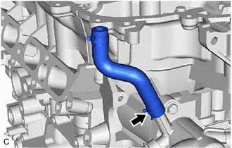
Install the No. 7 water by-pass hose to the water outlet and slide the clip to secure it.
16671
26.INSTALL WATER VALVE
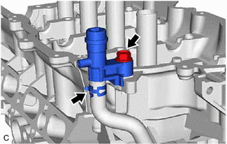
Install the water valve to the No. 7 water by-pass hose and slide the clip to secure it.
Connect the water valve to the camshaft housing sub-assembly with the bolt.
- Torque:
- 21 N*m (214 kgf*cm, 15 ft.*lbf)
13070A
27.INSTALL CAMSHAFT TIMING EXHAUST GEAR ASSEMBLY
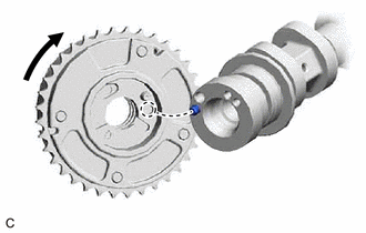
| *a | Knock Pin |
| *b | Knock Pin Hole |
Align and fit the knock pin of the No. 2 camshaft to the knock pin hole of the camshaft timing exhaust gear assembly.
- NOTICE:
-
Do not forcibly push in the camshaft timing exhaust gear assembly. This may cause the knock pin tip to damage the installation surface of the camshaft timing exhaust gear assembly.
- HINT:
-
Fit the No. 2 camshaft and camshaft timing exhaust gear assembly together by pushing camshaft timing exhaust gear assembly lightly against the No. 2 camshaft and rotating it to the left (counterclockwise).
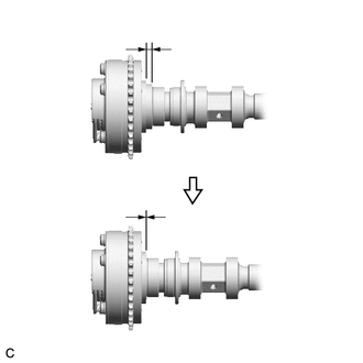
| *1 | Camshaft Timing Exhaust Gear Assembly |
| *2 | No. 2 Camshaft Flange |
| *a | No Gap |
Check that there is no gap between the camshaft timing exhaust gear assembly and No. 2 camshaft flange.
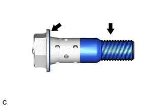
Apply engine oil to the areas of the camshaft timing gear bolt (for exhaust side) shown in the illustration.
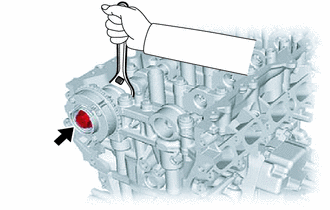
Tighten the camshaft timing gear bolt (for exhaust side) while holding the camshaft timing exhaust gear assembly.
- Torque:
- 95 N*m (969 kgf*cm, 70 ft.*lbf)
- NOTICE:
- ·
If the camshaft timing gear bolt (for exhaust side) has been struck or dropped, replace it.
·Do not use an impact wrench.
13050
28.INSTALL CAMSHAFT TIMING GEAR ASSEMBLY
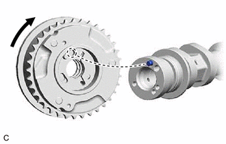
| *a | Knock Pin |
| *b | Knock Pin Hole |
Align and fit the knock pin of the camshaft to the knock pin hole of the camshaft timing gear assembly.
- NOTICE:
-
Do not forcibly push in the camshaft timing gear assembly. This may cause the knock pin tip to damage the installation surface of the camshaft timing gear assembly.
- HINT:
-
Fit the camshaft and camshaft timing gear assembly together by pushing camshaft timing gear assembly lightly against the camshaft and rotating it to the left (counterclockwise).
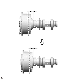
| *1 | Camshaft Timing Gear Assembly |
| *2 | Camshaft Flange |
| *a | No Gap |
Check that there is no gap between the camshaft timing gear assembly and camshaft flange.
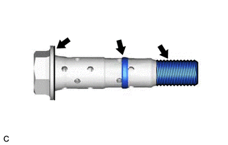
Apply engine oil to the areas of the camshaft timing gear bolt (for intake side) shown in the illustration.
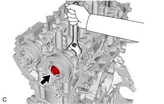
Tighten the camshaft timing gear bolt (for intake side) while holding the camshaft timing gear assembly.
- Torque:
- 95 N*m (969 kgf*cm, 70 ft.*lbf)
- NOTICE:
- ·
If the camshaft timing gear bolt (for intake side) has been struck or dropped, replace it.
·Do not use an impact wrench.
13507
29.INSTALL NO. 2 CHAIN SUB-ASSEMBLY
Temporarily install the crankshaft pulley set bolt to the crankshaft.
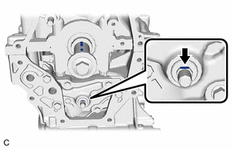
| *a | Crankshaft Timing Gear Key |
Set the crankshaft timing gear keys as shown in the illustration.
Turn the oil pump drive shaft so that the flat face upward.
Remove the crankshaft pulley set bolt from the crankshaft.
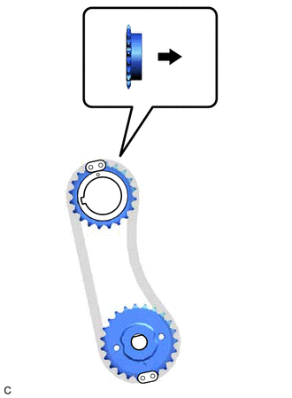
| *1 | Oil Pump Drive Gear |
| *2 | Oil Pump Drive Shaft Gear |
| *a | Mark Plate (Gold or Yellow) |
| *b | Timing Mark |
| *c | Crankshaft Timing Gear Key Groove |
|
|
Front of Engine |
Align the mark plates (gold or yellow) with the timing mark of the oil pump drive gear and oil pump drive shaft gear as shown in the illustration.
- HINT:
-
Make sure the mark plates (gold or yellow) of the No. 2 chain sub-assembly are facing away from the engine assembly.
With the No. 2 chain sub-assembly placed around the oil pump drive gear and oil pump drive shaft gear, install the oil pump drive gear to the crankshaft and temporarily install the oil pump drive shaft gear to the oil pump drive shaft.
Temporarily install the oil pump drive shaft gear nut.
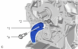
| *1 | Chain Tensioner Plate |
| *2 | Chain Damper Spring |
| *a | Bolt |
Install the chain damper spring to the chain tensioner plate, and then install the chain tensioner plate with the bolt.
- Torque:
- 10 N*m (102 kgf*cm, 7 ft.*lbf)
Temporarily install the crankshaft pulley assembly to the crankshaft with the crankshaft pulley set bolt.
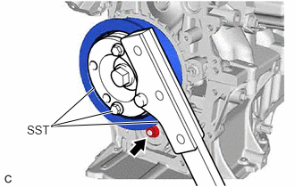
Using SST, hold the crankshaft pulley assembly. Then tighten the oil pump drive shaft gear nut.
- SST
- 09213-70011 (09213-70020)
09330-00021
- Torque:
- 28 N*m (286 kgf*cm, 21 ft.*lbf)
Remove SST, the crankshaft pulley set bolt and crankshaft pulley assembly.
13521
30.INSTALL CRANKSHAFT TIMING SPROCKET
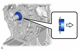
|
|
Front of Engine |
Install the crankshaft timing sprocket to the crankshaft.
31.SET NO. 1 CYLINDER TO TDC/COMPRESSION
Temporarily install the crankshaft pulley set bolt to the crankshaft.
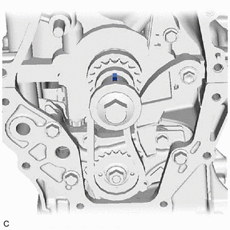
| *a | Crankshaft Timing Gear Key |
Turn the crankshaft clockwise until the crankshaft timing gear key is facing upward.
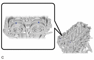
| *a | Timing Mark |
Check that the timing marks on the camshaft timing exhaust gear assembly and camshaft timing gear assembly are aligned as shown in the illustration.
Remove the crankshaft pulley set bolt from the crankshaft.
13506
32.INSTALL CHAIN SUB-ASSEMBLY
13559
33.INSTALL CHAIN TENSIONER SLIPPER
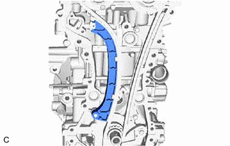
Install the chain tensioner slipper to the cylinder block sub-assembly.
13540
34.INSTALL NO. 1 CHAIN TENSIONER ASSEMBLY
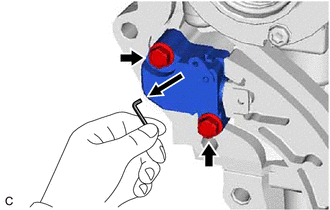
| *a | Pin |
Install the No. 1 chain tensioner assembly to the cylinder head sub-assembly with the 2 bolts.
- Torque:
- 10 N*m (102 kgf*cm, 7 ft.*lbf)
Remove the pin from the stopper plate hole.
35.CHECK NO. 1 CYLINDER TDC/COMPRESSION
Check that each timing mark is at TDC/compression.
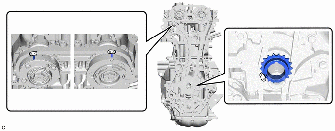
| *a | Timing Mark | *b | Mark Plate (Gold) |
16331A
36.INSTALL THERMOSTAT (for Cylinder Block)
16321
37.INSTALL WATER INLET
16322
38.INSTALL WATER INLET PIPE
Apply water to 2 new water inlet O-rings, and install the water inlet O-rings to the water inlet pipe.
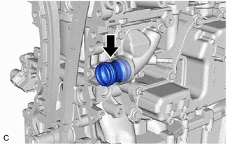
Install the water inlet pipe to the water inlet.
11302A
39.INSTALL TIMING CHAIN COVER OIL SEAL
11310
40.INSTALL TIMING CHAIN COVER ASSEMBLY
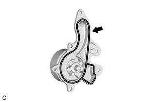
Install a new water pump gasket to the engine water pump assembly.
- HINT:
-
Be sure to clean the contact surfaces.
Temporarily install the engine water pump assembly to the timing chain cover assembly with the 4 bolts.
Remove any remaining seal packing.
Clean the contact surfaces of the timing chain cover assembly, camshaft housing sub-assembly, cylinder head sub-assembly, cylinder block sub-assembly and stiffening crankcase assembly, and confirm that no oil, moisture, or other foreign matter is on the surfaces.
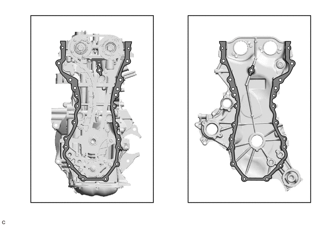
| *a | Engine Side | *b | Timing Chain Cover Assembly Side |

|
Clean | - | - |
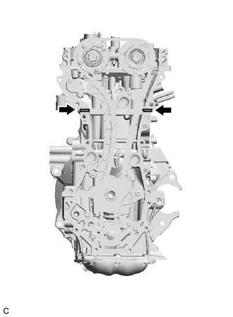
Apply seal packing to the engine unit as shown in the illustration.
- Seal Packing:
Toyota Genuine Seal Packing Black, Three Bond 1207B or equivalent
- Standard Seal Packing Diameter:
5.0 mm (0.197 in.)
- NOTICE:
-
Install the timing chain cover assembly within 3 minutes and tighten the bolts within 10 minutes of applying seal packing.
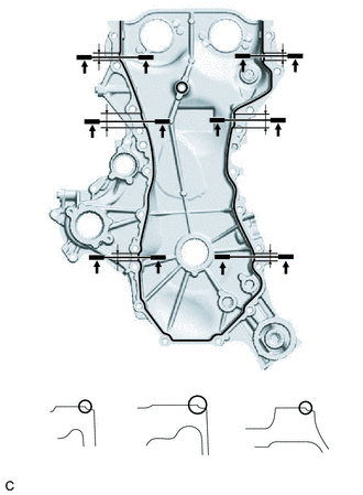
| *a | Seal Packing |
| *b | Thickness: 2.5 to 3.5 mm (0.0984 to 0.138 in.) Width: 6.0 to 8.0 mm (0.236 to 0.315 in.) |
| *c | Thickness: 2.5 to 3.5 mm (0.0984 to 0.138 in.) Width: 14.0 to 16.0 mm (0.551 to 0.630 in.) |
| *d | 9.1 mm (0.358 in.) |
| *e | 19.9 mm (0.783 in.) |
| *f | 7.9 mm (0.311 in.) |
| *g | 8.3 mm (0.327 in.) |
| *h | 20.0 mm (0.787 in.) |
| *i | 8.1 mm (0.319 in.) |
Apply seal packing to the timing chain cover assembly as shown in the illustration.
- Seal Packing:
Toyota Genuine Seal Packing Black, Three Bond 1207B or equivalent
- Standard Seal Packing Diameter:
2.5 to 3.5 mm (0.0984 to 0.138 in.)
- NOTICE:
-
Install the timing chain cover assembly within 3 minutes and tighten the bolts within 10 minutes of applying seal packing.
Install the timing chain cover assembly.
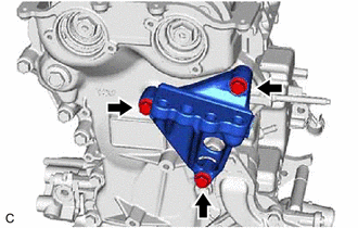
Temporarily install the engine mounting bracket RH with the 3 bolts.
- NOTICE:
-
Make sure that there is no oil on the threads of the bolts.
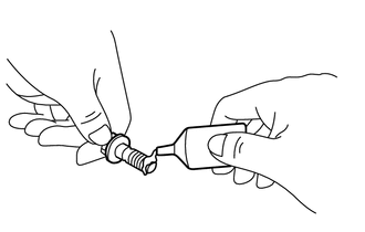
| *a | Adhesive |
Apply adhesive to the threads of the 2 bolts (B).
- Adhesive:
Toyota Genuine Adhesive 1324, Three bond 1324 or equivalent
- NOTICE:
-
Make sure that there is no oil on the threads of the bolts.
Tighten the 26 bolts in the order shown in the illustration.
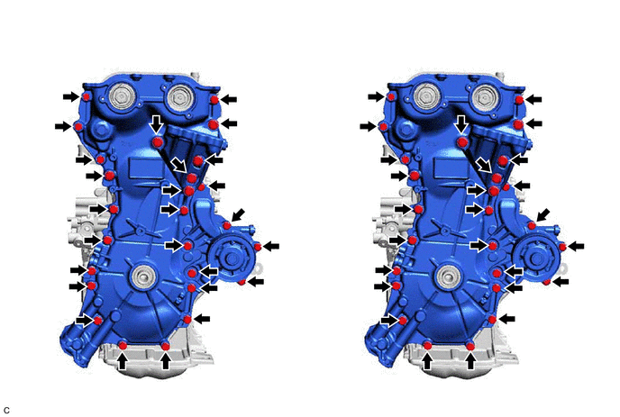
| *a | Torque | *b | Bolt Tightening Order |
- Torque:
- Bolt (A), (B), (D), (E) : 21 N*m (214 kgf*cm, 15 ft.*lbf)
- Bolt (C), (F) : 43 N*m (438 kgf*cm, 32 ft.*lbf)
- NOTICE:
- ·
Tighten the bolts within 10 minutes of applying seal packing.
·Do not add engine oil for at least 2 hours after installation.
·Do not start the engine for at least 2 hours after installation.
·Make sure that there is no oil on the threads of the bolts.
- HINT:
-
Using a 12 mm union nut wrench, tighten the bolt (A).
16326
41.INSTALL NO. 2 WATER INLET HOUSING GASKET
16031
42.INSTALL WATER INLET WITH THERMOSTAT SUB-ASSEMBLY
13470
43.INSTALL CRANKSHAFT PULLEY ASSEMBLY
15600A
44.INSTALL OIL FILTER UNION
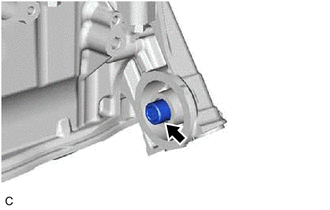
Using a 12 mm hexagon socket wrench, install the oil filter union to the timing chain cover assembly.
- Torque:
- 29.5 N*m (301 kgf*cm, 22 ft.*lbf)
15601
45.INSTALL OIL FILTER SUB-ASSEMBLY
11191A
46.INSTALL SPARK PLUG TUBE GASKET
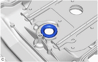
Install 4 new spark plug tube gaskets to the cylinder head cover sub-assembly.
11213
47.INSTALL CYLINDER HEAD COVER GASKET
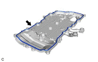
Install a new cylinder head cover gasket to the cylinder head cover sub-assembly.
- NOTICE:
-
Remove any oil from the contact surfaces.
48.ADD ENGINE OIL
- HINT:
-
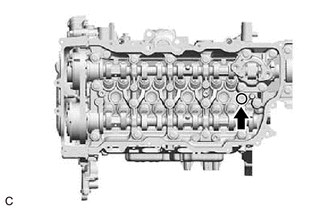
-
Before installing the cylinder head cover sub-assembly, pour engine oil into the oil hole shown in the illustration until the oil hole is filled with engine oil.
11201
49.INSTALL CYLINDER HEAD COVER SUB-ASSEMBLY
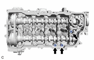
Install 3 new gaskets to the locations shown in the illustration.
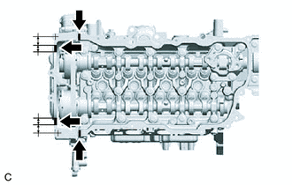
| *a | 18.0 mm (0.709 in.) |
| *b | 17.0 mm (0.669 in.) |
| *c | 21.0 mm (0.827 in.) |
Apply seal packing as shown in the illustration.
- Seal Packing:
Toyota Genuine Seal Packing Black, Three Bond 1207B or equivalent
- Standard Seal Packing Diameter:
2.0 to 3.0 mm (0.0787 to 0.118 in.)
- NOTICE:
- ·
Remove any oil from the contact surfaces.
·Install the cylinder head cover sub-assembly within 3 minutes and tighten the bolts within 15 minutes of applying seal packing.
·Do not add engine oil for at least 2 hours after installation.
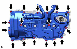
| *1 | Cylinder Head Cover Seal Washer |
Install the cylinder head cover sub-assembly to the camshaft housing sub-assembly with the 17 bolts and 2 new cylinder head cover seal washers in the order shown in the illustration.
- Torque:
- 10 N*m (102 kgf*cm, 7 ft.*lbf)
15010
50.INSTALL OIL PUMP RELIEF VALVE HOUSING ASSEMBLY
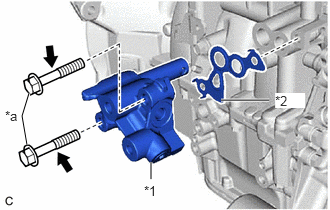
| *1 | Oil Pump Relief Valve Housing Assembly |
| *2 | Oil Regulator Body Gasket |
| *a | Bolt |
Install a new oil regulator body gasket to the oil pump relief valve housing assembly as shown in the illustration.
Install the oil pump relief valve housing assembly to the cylinder block sub-assembly with the 2 bolts.
- Torque:
- 21 N*m (214 kgf*cm, 15 ft.*lbf)
51.INSTALL OIL PRESSURE SWITCHING VALVE ASSEMBLY
83520
52.INSTALL OIL PRESSURE SENDER GAUGE ASSEMBLY
89429F
53.INSTALL ENGINE OIL TEMPERATURE SENSOR
11301K
54.INSTALL CRANKSHAFT POSITION SENSOR
89615
55.INSTALL KNOCK CONTROL SENSOR
12511D
56.INSTALL GENERATOR BRACKET
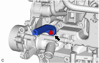
Install the generator bracket to the cylinder block sub-assembly with the bolt.
- Torque:
- 21 N*m (214 kgf*cm, 15 ft.*lbf)
11452
57.INSTALL ENGINE OIL LEVEL DIPSTICK GUIDE
- HINT:
-
There are two types of engine oil level dipstick guide.
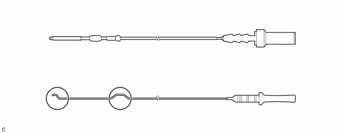 0.75,0.396 6.542,2.458 5.792,2.063 0.76,1.458 6.531,1.458 false 1.427,2.167 1.865,2.271 1.865,2.271 2.292,2.167 false 0.823,0.448 1.198,0.688 0.375,0.24 12 false *A 0.833,1.521 1.208,1.76 0.375,0.24 12 false *B 1.771,2.281 2.083,2.479 0.313,0.198 10 false *a
*A Type A *B Type B *a Protrusion - -
Apply a light coat of engine oil to a new engine oil level dipstick guide O-ring and install it to the engine oil level dipstick guide.
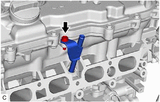
Install the engine oil level dipstick guide to the camshaft housing sub-assembly with the bolt.
- Torque:
- 10 N*m (102 kgf*cm, 7 ft.*lbf)
Install the engine oil level dipstick to the engine oil level dipstick guide.
- NOTICE:
-
If the vehicle is equipped with a Type B engine oil level dipstick, make sure to insert it with the protrusion facing toward the intake manifold.
15370
58.INSTALL CAMSHAFT TIMING OIL CONTROL SOLENOID ASSEMBLY (for Exhaust Side)
15370
59.INSTALL CAMSHAFT TIMING OIL CONTROL SOLENOID ASSEMBLY (for Intake Side)
60.INSTALL CAMSHAFT POSITION SENSOR (for Exhaust Side)
61.INSTALL CAMSHAFT POSITION SENSOR (for Intake Side)
19100P
62.INSTALL SPARK PLUG
12108A
63.INSTALL OIL FILLER CAP GASKET
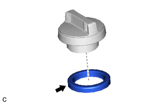
Install the oil filler cap gasket to the oil filler cap assembly.
12180E
64.INSTALL OIL FILLER CAP ASSEMBLY
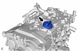
Install the oil filler cap assembly to the cylinder head cover sub-assembly.