NR Series ENGINE MECHANICAL ENGINE UNIT DISASSEMBLY
PROCEDURE

 12180E
1.REMOVE OIL FILLER CAP ASSEMBLY
12180E
1.REMOVE OIL FILLER CAP ASSEMBLY
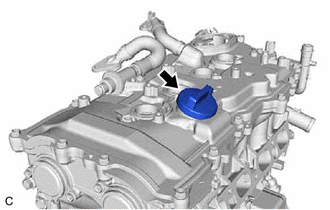
Remove the oil filler cap assembly from the cylinder head cover sub-assembly.
12108A
2.REMOVE OIL FILLER CAP GASKET
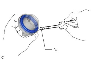
| *a | Protective Tape |
Using a screwdriver with its tip wrapped with protective tape, remove the oil filler cap gasket from the oil filler cap assembly.
19100P
3.REMOVE SPARK PLUG
4.REMOVE CAMSHAFT POSITION SENSOR (for Intake Side)
5.REMOVE CAMSHAFT POSITION SENSOR (for Exhaust Side)
15370
6.REMOVE CAMSHAFT TIMING OIL CONTROL SOLENOID ASSEMBLY (for Intake Side)
15370
7.REMOVE CAMSHAFT TIMING OIL CONTROL SOLENOID ASSEMBLY (for Exhaust Side)
11452
8.REMOVE ENGINE OIL LEVEL DIPSTICK GUIDE
Remove the engine oil level dipstick from the engine oil level dipstick guide.
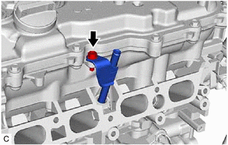
Remove the bolt and engine oil level dipstick guide from the camshaft housing sub-assembly.
Remove the engine oil level dipstick guide O-ring from the engine oil level dipstick guide.
12511D
9.REMOVE GENERATOR BRACKET
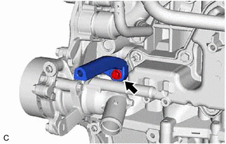
Remove the bolt and generator bracket from the cylinder block sub-assembly.
89615
10.REMOVE KNOCK CONTROL SENSOR
11301K
11.REMOVE CRANKSHAFT POSITION SENSOR
89429F
12.REMOVE ENGINE OIL TEMPERATURE SENSOR
83520
13.REMOVE OIL PRESSURE SENDER GAUGE ASSEMBLY
14.REMOVE OIL PRESSURE SWITCHING VALVE ASSEMBLY
15010
15.REMOVE OIL PUMP RELIEF VALVE HOUSING ASSEMBLY
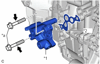
| *1 | Oil Pump Relief Valve Housing Assembly |
| *2 | Oil Regulator Body Gasket |
| *a | Bolt |
Remove the 2 bolts, oil pump relief valve housing assembly and oil regulator body gasket from the cylinder block sub-assembly.
11201
16.REMOVE CYLINDER HEAD COVER SUB-ASSEMBLY
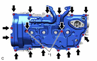
| *1 | Cylinder Head Cover Seal Washer |
Remove the 17 bolts, 2 cylinder head cover seal washers, and cylinder head cover sub-assembly from the camshaft housing sub-assembly.
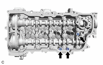
Remove the 3 gaskets from the camshaft bearing cap.
- NOTICE:
-
As gaskets may stick to the cylinder head cover sub-assembly, be careful not to drop any of the gaskets into the engine when removing the cylinder head cover sub-assembly.
11213
17.REMOVE CYLINDER HEAD COVER GASKET
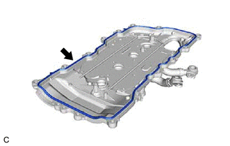
Remove the cylinder head cover gasket from the cylinder head cover sub-assembly.
11191A
18.REMOVE SPARK PLUG TUBE GASKET
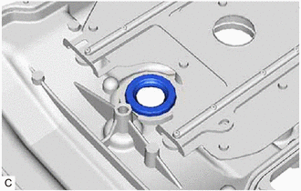
Remove the 4 spark plug tube gaskets from the cylinder head cover sub-assembly.
15601
19.REMOVE OIL FILTER SUB-ASSEMBLY
15600A
20.REMOVE OIL FILTER UNION
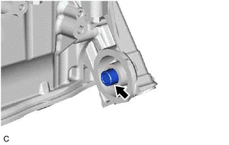
Using a 12 mm hexagon socket wrench, remove the oil filter union from the timing chain cover assembly.
21.SET NO. 1 CYLINDER TO TDC/COMPRESSION
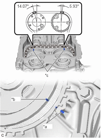
| *a | Timing Mark (TDC) |
| *b | Cutout |
| *c | Timing Mark |
Turn the crankshaft pulley assembly until its cutout is aligned with the timing mark (TDC) of the timing chain cover assembly.
Check that the timing marks on both the camshaft timing exhaust gear assembly and camshaft timing gear assembly are facing upward as shown in the illustration.
- HINT:
-
If the timing marks are not facing upwards, turn the crankshaft 1 complete revolution (360°) and align the timing marks as above.
13470
22.REMOVE CRANKSHAFT PULLEY ASSEMBLY
16031
23.REMOVE WATER INLET WITH THERMOSTAT SUB-ASSEMBLY
16326
24.REMOVE NO. 2 WATER INLET HOUSING GASKET
12315A
25.REMOVE ENGINE MOUNTING BRACKET RH
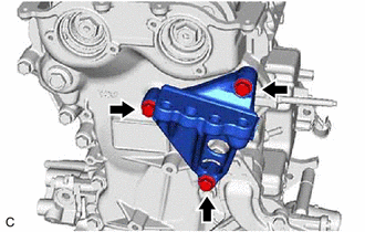
Remove the 3 bolts and engine mounting bracket RH from the timing chain cover assembly.
26.REMOVE ENGINE WATER PUMP ASSEMBLY
11310
27.REMOVE TIMING CHAIN COVER ASSEMBLY
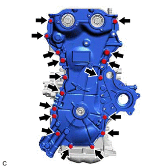
Remove the 17 bolts from the timing chain cover assembly.
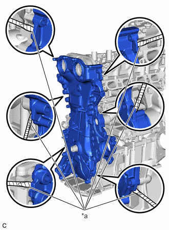
| *a | Protective Tape |
Remove the timing chain cover assembly by prying between the timing chain cover assembly and cylinder head sub-assembly, camshaft housing sub-assembly, cylinder block sub-assembly and stiffening crankcase assembly with a screwdriver with its tip wrapped with protective tape.
- NOTICE:
-
Be careful not to damage the contact surfaces of the cylinder head sub-assembly, camshaft housing sub-assembly, cylinder block sub-assembly, stiffening crankcase assembly and timing chain cover assembly.
11302A
28.REMOVE TIMING CHAIN COVER OIL SEAL
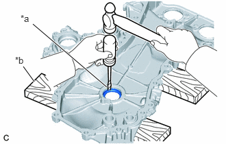
| *a | Protective Tape |
| *b | Wooden Block |
Place the timing chain cover assembly on wooden blocks.
Using a hammer and a screwdriver with its tip wrapped with protective tape, tap out the timing chain cover oil seal.
- NOTICE:
-
Be careful not to damage the timing chain cover assembly.
16322
29.REMOVE WATER INLET PIPE
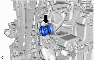
Remove the water inlet pipe from the water inlet.
Remove the 2 water inlet O-rings from the water inlet pipe.
16321
30.REMOVE WATER INLET
16331A
31.REMOVE THERMOSTAT (for Cylinder Block)
13540
32.REMOVE NO. 1 CHAIN TENSIONER ASSEMBLY
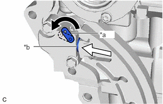
| *a | Stopper Plate |
| *b | Plunger |

|
Push |
Turn the stopper plate of the No. 1 chain tensioner assembly counterclockwise to release the lock and push in the plunger.
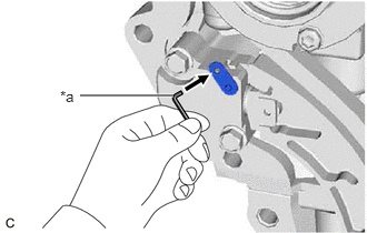
| *a | Pin |
Turn the stopper plate clockwise to set the lock, and insert a pin into the stopper plate hole.
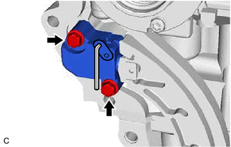
Remove the 2 bolts and No. 1 chain tensioner assembly from the cylinder head sub-assembly.
13559
33.REMOVE CHAIN TENSIONER SLIPPER
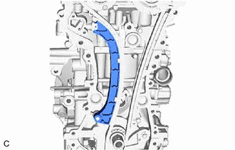
Remove the chain tensioner slipper from the cylinder block sub-assembly.
13566B
34.REMOVE TIMING CHAIN GUIDE
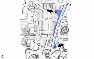
Remove the 2 bolts and timing chain guide from the cylinder block sub-assembly and cylinder head sub-assembly.
13506
35.REMOVE CHAIN SUB-ASSEMBLY
13521
36.REMOVE CRANKSHAFT TIMING SPROCKET
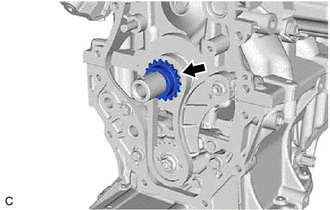
Remove the crankshaft timing sprocket from the crankshaft.
13507
37.REMOVE NO. 2 CHAIN SUB-ASSEMBLY
Temporarily install the crankshaft pulley assembly with the crankshaft pulley set bolt.
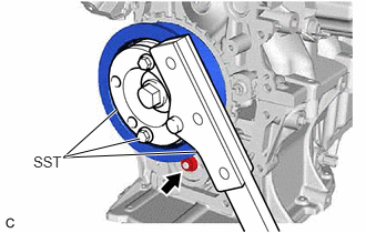
Using SST, hold the crankshaft pulley assembly. Then remove the oil pump drive shaft gear nut.
- SST
- 09213-70011 (09213-70020)
09330-00021
Remove SST, the crankshaft pulley set bolt and crankshaft pulley assembly.
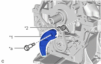
| *1 | Chain Tensioner Plate |
| *2 | Chain Damper Spring |
| *a | Bolt |
Remove the bolt, chain tensioner plate and chain damper spring.
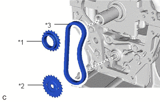
| *1 | Oil Pump Drive Gear |
| *2 | Oil Pump Drive Shaft Gear |
| *3 | No. 2 Chain Sub-assembly |
Remove the oil pump drive gear, oil pump drive shaft gear and No. 2 chain sub-assembly.
13050
38.REMOVE CAMSHAFT TIMING GEAR ASSEMBLY
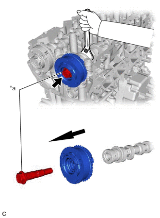
| *a | Camshaft Timing Gear Bolt (for Intake Side) |
Remove the camshaft timing gear bolt (for intake side) while holding the hexagonal portion of the camshaft, and then remove the camshaft timing gear assembly.
- NOTICE:
- ·
If the camshaft timing gear bolt (for intake side) has been struck or dropped, replace it.
·Keep the camshaft timing gear assembly horizontal while removing it from the camshaft.
·Do not disassemble the camshaft timing gear assembly.
13070A
39.REMOVE CAMSHAFT TIMING EXHAUST GEAR ASSEMBLY
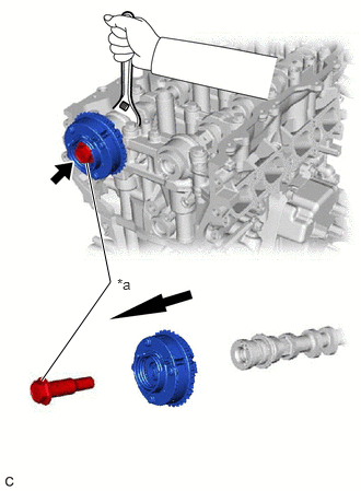
| *a | Camshaft Timing Gear Bolt (for Exhaust Side) |
Remove the camshaft timing gear bolt (for exhaust side) while holding the hexagonal portion of the No. 2 camshaft, and then remove the camshaft timing exhaust gear assembly.
- NOTICE:
- ·
If the camshaft timing gear bolt (for exhaust side) has been struck or dropped, replace it.
·Keep the camshaft timing exhaust gear assembly horizontal while removing it from the No. 2 camshaft.
·Do not disassemble the camshaft timing exhaust gear assembly.
40.REMOVE CAMSHAFT BEARING CAP
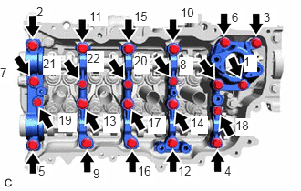
Uniformly loosen and remove the 22 bolts in the order shown in the illustration.
- NOTICE:
-
Make sure that the camshaft and No. 2 camshaft remain level while uniformly loosening the bolts.
Remove the 5 camshaft bearing caps from the camshaft housing sub-assembly.
- HINT:
-
Arrange the removed parts in such a way that they can be reinstalled to their original locations.
13512
42.REMOVE NO. 2 CAMSHAFT
15678A
43.REMOVE OIL CONTROL VALVE FILTER
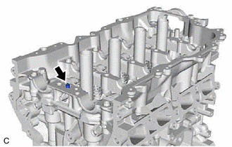
Remove the oil control valve filter from the camshaft housing sub-assembly.
16671
44.REMOVE WATER VALVE
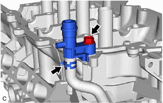
Remove the bolt to disconnect the water valve from the camshaft housing sub-assembly.
Slide the clip and remove the water valve from the No. 7 water by-pass hose.
16295
45.REMOVE NO. 7 WATER BY-PASS HOSE
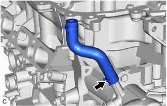
Slide the clip and remove the No. 7 water by-pass hose from the water outlet.
82125N
46.REMOVE NO. 5 ENGINE WIRE
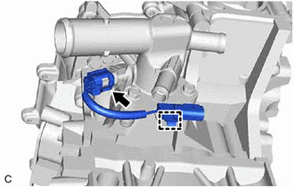
Disconnect the engine coolant temperature sensor connector.
Disengage the wire harness clamp and remove the No. 5 engine wire from the water outlet.
89422A
47.REMOVE ENGINE COOLANT TEMPERATURE SENSOR
48.REMOVE WATER OUTLET
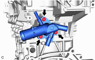
Remove the 3 bolts and water outlet from the cylinder head sub-assembly.
16341
49.REMOVE WATER OUTLET GASKET
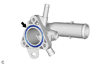
Remove the water outlet gasket from the water outlet.
11103
50.REMOVE CAMSHAFT HOUSING SUB-ASSEMBLY
13801
51.REMOVE NO. 1 VALVE ROCKER ARM SUB-ASSEMBLY
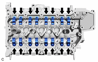
Remove the 16 No. 1 valve rocker arm sub-assemblies from the cylinder head sub-assembly.
- HINT:
-
Arrange the removed parts in such a way that they can be reinstalled to their original locations.
13750
52.REMOVE VALVE LASH ADJUSTER ASSEMBLY
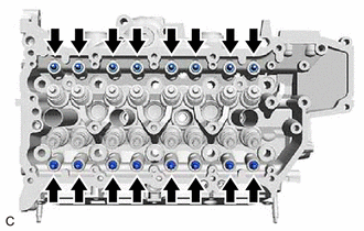
Remove the 16 valve lash adjuster assemblies from the cylinder head sub-assembly.
- HINT:
-
Arrange the removed parts in such a way that they can be reinstalled to their original locations.
13716
53.REMOVE VALVE STEM CAP
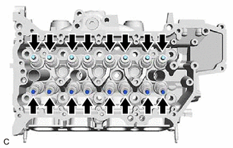
Remove the 16 valve stem caps from the cylinder head sub-assembly.
- HINT:
-
Arrange the removed parts in such a way that they can be reinstalled to their original locations.
11101
54.REMOVE CYLINDER HEAD SUB-ASSEMBLY
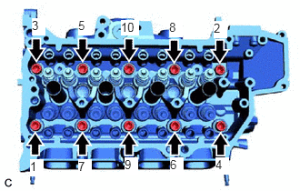
Using a 10 mm bi-hexagon socket wrench, uniformly loosen and remove the 10 cylinder head set bolts and 10 cylinder head set plate washers in several steps in the order shown in the illustration.
- NOTICE:
- ·
Do not drop the cylinder head set plate washers into the cylinder head sub-assembly.
·Removing the cylinder head set bolts in the incorrect order may cause warpage or cracking of the cylinder head sub-assembly.
- HINT:
-
Arrange the removed parts in such a way that they can be reinstalled to their original locations.
Remove the cylinder head sub-assembly.
11115
55.REMOVE CYLINDER HEAD GASKET
11445
56.REMOVE CYLINDER BLOCK WATER JACKET SPACER
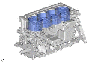
Remove the cylinder block water jacket spacer from the cylinder block sub-assembly.
12101A
57.REMOVE OIL PAN DRAIN PLUG
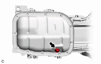
Remove the oil pan drain plug and oil pan drain plug gasket from the No. 2 oil pan sub-assembly.
12102A
58.REMOVE NO. 2 OIL PAN SUB-ASSEMBLY
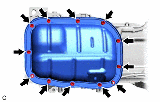
Remove the 10 bolts and 2 nuts from the No. 2 oil pan sub-assembly.
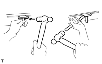
Insert the blade of an oil pan seal cutter between the stiffening crankcase assembly and No. 2 oil pan sub-assembly. Cut through the applied sealer and remove the No. 2 oil pan sub-assembly.
- NOTICE:
- ·
Be careful not to damage the surface of the No. 2 oil pan sub-assembly which contacts the stiffening crankcase assembly.
·Be careful not to damage the flange of the stiffening crankcase assembly.
59.REMOVE STUD BOLT
- NOTICE:
-
If a stud bolt is deformed or its threads are damaged, replace it.
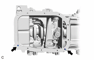
Using an E6 "TORX" socket wrench, remove the 2 stud bolts from the stiffening crankcase assembly.
15100
60.REMOVE OIL PUMP ASSEMBLY
89491
61.REMOVE ENGINE OIL LEVEL SENSOR
89439
62.REMOVE SENSOR BRACKET
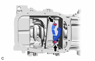
Remove the 2 bolts and sensor bracket from the stiffening crankcase assembly.
11420
63.REMOVE STIFFENING CRANKCASE ASSEMBLY
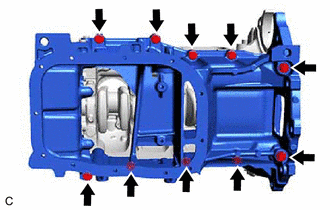
Uniformly loosen and remove the 10 bolts from the stiffening crankcase assembly.
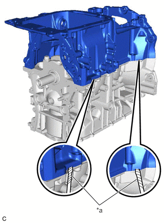
| *a | Protective Tape |
Remove the stiffening crankcase assembly by prying between the stiffening crankcase assembly and cylinder block sub-assembly with a screwdriver with its tip wrapped with protective tape.
- NOTICE:
-
Be careful not to damage the contact surfaces of the stiffening crankcase assembly and cylinder block sub-assembly.
11401L
64.REMOVE REAR ENGINE OIL SEAL
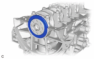
Remove the rear engine oil seal from the cylinder block sub-assembly.
- NOTICE:
-
Be careful not to damage the crankshaft.
11434Y
65.REMOVE RING PIN
- NOTICE:
-
It is not necessary to remove ring pins unless they are being replaced.
11151A
66.REMOVE CAMSHAFT BEARING CAP SETTING RING PIN
- HINT:
-
It is not necessary to remove a camshaft bearing cap setting ring pins unless they are being replaced.
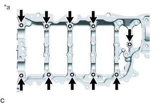
| *a | Camshaft Housing Sub-assembly Top Side |
Remove the 10 camshaft bearing cap setting ring pins from the camshaft housing sub-assembly.