NR Series ENGINE MECHANICAL ENGINE UNIT INSPECTION
PROCEDURE

 13801
1.INSPECT NO. 1 VALVE ROCKER ARM SUB-ASSEMBLY
13801
1.INSPECT NO. 1 VALVE ROCKER ARM SUB-ASSEMBLY
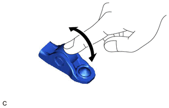
Turn the roller by hand to check that it turns smoothly.
- HINT:
-
If the roller does not turn smoothly, replace the No. 1 valve rocker arm sub-assembly.
13750
2.INSPECT VALVE LASH ADJUSTER ASSEMBLY
- NOTICE:
- ·
Keep the valve lash adjuster assembly free from dirt and foreign matter.
·Only use clean engine oil.
Place the valve lash adjuster assembly into a container filled with engine oil.
Insert the tip of SST into the valve lash adjuster assembly plunger and use the tip to press down on the check ball inside the plunger.
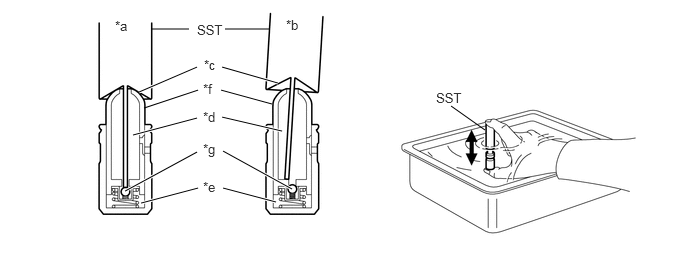
| *a | Correct | *b | Incorrect |
| *c | Taper | *d | Low Pressure Chamber |
| *e | High Pressure Chamber | *f | Plunger |
| *g | Check Ball | - | - |
- SST
- 09276-75010
Squeeze SST and the valve lash adjuster assembly together to move the plunger up and down 5 to 6 times.
Check the movement of the plunger and bleed the air.
- OK:
Plunger moves up and down.
- NOTICE:
-
When bleeding the air from the high-pressure chamber, make sure that the tip of SST is actually pressing the check ball as shown in the illustration. If the check ball is not pressed, air will not bleed.
After bleeding the air, remove SST. Then try to quickly and firmly press the plunger by hand.
- OK:
Plunger is very difficult to move.
- HINT:
-
If the plunger is easy to move, replace the valve lash adjuster assembly.
13506
3.INSPECT CHAIN SUB-ASSEMBLY
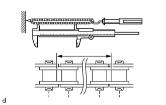
| *a | Measurement Length |
Using a spring scale, pull the chain sub-assembly with a force of 147 N (15 kgf, 33.0 lbf) as shown in the illustration.
Using a vernier caliper, measure the length of 15 links.
- Maximum Chain Elongation:
121.6 mm (4.79 in.)
- NOTICE:
-
Perform the measurement at 3 random places. Use the average of the measurements.
- HINT:
-
If the average elongation is more than the maximum, replace the chain sub-assembly.
13507
4.INSPECT NO. 2 CHAIN SUB-ASSEMBLY
| *a | Measurement Length |
Using a spring scale, pull the No. 2 chain sub-assembly with a force of 147 N (15 kgf, 33.0 lbf) as shown in the illustration.
Using a vernier caliper, measure the length of 15 links.
- Maximum Chain Elongation:
107.0 mm (4.21 in.)
- NOTICE:
-
Perform the measurement at 3 random places. Use the average of the measurements.
- HINT:
-
If the average elongation is more than the maximum, replace the No. 2 chain sub-assembly.
13540
5.INSPECT NO. 1 CHAIN TENSIONER ASSEMBLY
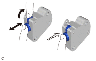
| *a | Raise |
| *b | Move |
| *c | Lock |
Check that the plunger moves smoothly when the cam is raised with your finger.
Release the cam, then check that the plunger is locked in place by the cam and does not move when pushed with your finger.
- HINT:
-
If the plunger does not move smoothly, replace the No. 1 chain tensioner assembly.
13050
6.INSPECT CAMSHAFT TIMING GEAR ASSEMBLY
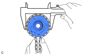
Place the chain sub-assembly around the camshaft timing gear assembly.
Using a vernier caliper, measure the diameter of the camshaft timing gear assembly and chain sub-assembly.
- Minimum Gear Diameter (with Chain Sub-assembly):
100.89 mm (3.97 in.)
- NOTICE:
-
The vernier caliper must be in contact with the chain rollers when measuring.
- HINT:
-
If the diameter is less than the minimum, replace the chain sub-assembly and camshaft timing gear assembly.
13070A
7.INSPECT CAMSHAFT TIMING EXHAUST GEAR ASSEMBLY

Place the chain sub-assembly around the camshaft timing exhaust gear assembly.
Using a vernier caliper, measure the diameter of the camshaft timing exhaust gear assembly and chain sub-assembly.
- Minimum Gear Diameter (with Chain Sub-assembly):
100.89 mm (3.97 in.)
- NOTICE:
-
The vernier caliper must be in contact with the chain rollers when measuring.
- HINT:
-
If the diameter is less than the minimum, replace the chain sub-assembly and camshaft timing exhaust gear assembly.
13519
8.INSPECT OIL PUMP DRIVE GEAR
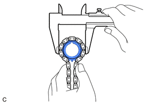
Place the No. 2 chain sub-assembly around the oil pump drive gear.
Using a vernier caliper, measure the diameter of the oil pump drive gear and No. 2 chain sub-assembly.
- Minimum Gear Diameter (with No. 2 Chain Sub-assembly):
52.55 mm (2.07 in.)
- NOTICE:
-
The vernier caliper must be in contact with the chain rollers when measuring.
- HINT:
-
If the diameter is less than the minimum, replace the No. 2 chain sub-assembly and oil pump drive gear.
15163
9.INSPECT OIL PUMP DRIVE SHAFT GEAR
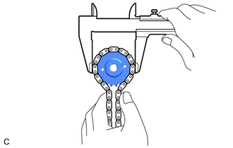
Place the No. 2 chain sub-assembly around the oil pump drive shaft gear.
Using a vernier caliper, measure the diameter of the oil pump drive shaft gear and No. 2 chain sub-assembly.
- Minimum Gear Diameter (with No. 2 Chain Sub-assembly):
59.21 mm (2.33 in.)
- NOTICE:
-
The vernier caliper must be in contact with the chain rollers when measuring.
- HINT:
-
If the diameter is less than the minimum, replace the No. 2 chain sub-assembly and oil pump drive shaft gear.
13521
10.INSPECT CRANKSHAFT TIMING SPROCKET
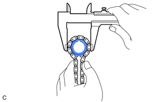
Place the chain sub-assembly around the crankshaft timing sprocket.
Using a vernier caliper, measure the diameter of the crankshaft timing sprocket and chain sub-assembly.
- Minimum Gear Diameter (with Chain Sub-assembly):
55.17 mm (2.17 in.)
- NOTICE:
-
The vernier caliper must be in contact with the chain rollers when measuring.
- HINT:
-
If the diameter is less than the minimum, replace the chain sub-assembly and crankshaft timing sprocket.
13559
11.INSPECT CHAIN TENSIONER SLIPPER
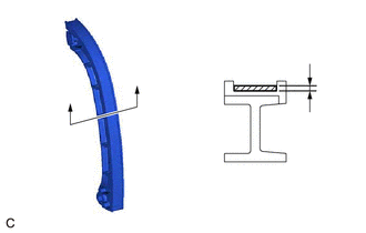
| *a | Depth |
Using a vernier caliper, measure the wear depth of the chain tensioner slipper.
- Maximum Depth:
1.0 mm (0.0394 in.)
- HINT:
-
If the depth is more than the maximum, replace the chain tensioner slipper.
13566B
12.INSPECT TIMING CHAIN GUIDE
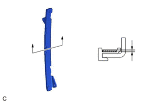
| *a | Depth |
Using a vernier caliper, measure the wear depth of the timing chain guide.
- Maximum Depth:
1.0 mm (0.0394 in.)
- HINT:
-
If the depth is more than the maximum, replace the timing chain guide.
13549
13.INSPECT CHAIN TENSIONER PLATE
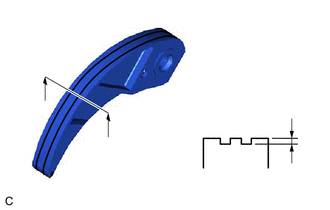
| *a | Depth |
Using a vernier caliper, measure the wear depth of the chain tensioner plate.
- Maximum Depth:
0.5 mm (0.0197 in.)
- HINT:
-
If the depth is more than the maximum, replace the chain tensioner plate.
11101A
14.INSPECT CYLINDER HEAD SET BOLT
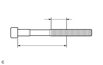
| *a | Measurement Area |
| *b | 115 mm (4.53 in.) |
Using a vernier caliper, measure the diameter of the threads at several points within the area shown in the illustration.
- Standard Diameter:
10.85 to 11.00 mm (0.427 to 0.433 in.)
- Minimum Diameter:
10.6 mm (0.417 in.)
- NOTICE:
- ·
Diameter measurements should be done at several points.
·If the diameter is less than the minimum, replace the cylinder head set bolt with a new one. Failure to do so may lead to engine damage.
·If there is any thread deformation, replace the cylinder head set bolt with a new one.
13511
15.INSPECT CAMSHAFT
Inspect the camshaft for runout.
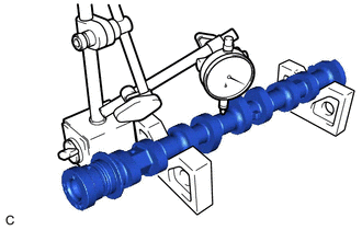
Place the camshaft on V-blocks.
Using a dial indicator, measure the runout at the center journal.
- Maximum Runout:
0.04 mm (0.00157 in.)
- HINT:
-
If the runout is more than the maximum, replace the camshaft.
Inspect the cam lobes.
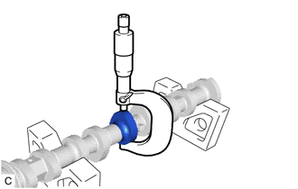
Using a micrometer, measure the cam lobe height.
- Standard Cam Lobe Height:
41.699 to 41.799 mm (1.64169 to 1.64563 in.)
- Minimum Cam Lobe Height:
41.649 mm (1.63972 in.)
- HINT:
-
If the cam lobe height is less than the minimum, replace the camshaft.
Inspect the camshaft journals.
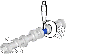
Using a micrometer, measure the journal diameter.
- Standard Journal Diameter:
Item Specified Condition No. 1 journal 34.449 to 34.465 mm (1.35626 to 1.35689 in.) Other journals 22.954 to 22.970 mm (0.90370 to 0.90433 in.)
- HINT:
-
If the journal diameter is not as specified, check the camshaft oil clearance.
13512
16.INSPECT NO. 2 CAMSHAFT
Inspect the No. 2 camshaft for runout.
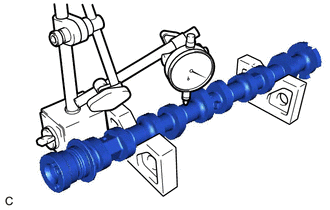
Place the No. 2 camshaft on V-blocks.
Using a dial indicator, measure the runout at the center journal.
- Maximum Runout:
0.04 mm (0.00157 in.)
- HINT:
-
If the runout is more than the maximum, replace the No. 2 camshaft.
Inspect the cam lobes.
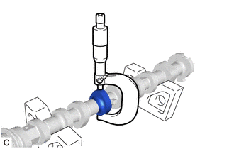
Using a micrometer, measure the cam lobe height.
- Standard Cam Lobe Height:
Item Specified Condition except Fuel Pump Assembly 40.481 to 40.581 mm (1.59374 to 1.59767 in.) for Fuel Pump Assembly 39.550 to 39.650 mm (1.55708 to 1.56102 in.)
- Minimum Cam Lobe Height:
Item Specified Condition except Fuel Pump Assembly 40.331 mm (1.58783 in.) for Fuel Pump Assembly 39.500 mm (1.55512 in.)
- HINT:
-
If the cam lobe height is less than the minimum, replace the No. 2 camshaft.
Inspect the No. 2 camshaft journals.
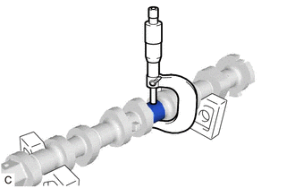
Using a micrometer, measure the journal diameter.
- Standard Journal Diameter:
Item Specified Condition No. 1 journal 34.449 to 34.465 mm (1.35626 to 1.35689 in.) Other journal 22.954 to 22.970 mm (0.90370 to 0.90433 in.)
- HINT:
-
If the journal diameter is not as specified, check the No. 2 camshaft oil clearance.
17.INSPECT CAMSHAFT THRUST CLEARANCE
Clean the camshaft, No. 2 camshaft and camshaft bearing caps.
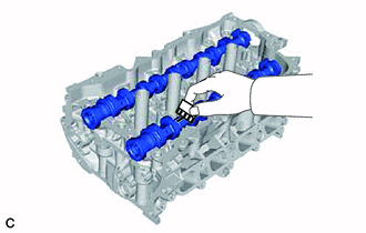
Place the camshaft and No. 2 camshaft on the camshaft housing sub-assembly.
Install the camshaft housing sub-assembly.
Install the camshaft bearing caps.
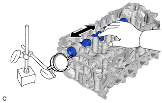
Using a dial indicator, measure the thrust clearance while moving the camshaft and No. 2 camshaft back and forth.
- Standard Thrust Clearance:
0.06 to 0.20 mm (0.00236 to 0.00787 in.)
- Maximum Thrust Clearance:
0.25 mm (0.00984 in.)
- HINT:
-
If the thrust clearance is more than the maximum, replace the camshaft housing sub-assembly. If the thrust surface is damaged, replace the camshaft.
18.INSPECT CAMSHAFT OIL CLEARANCE
Clean the camshaft bearing caps and camshaft journals.
Place the camshaft and No. 2 camshaft on the camshaft housing sub-assembly.
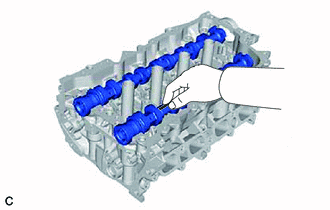
| *a | Plastigage |
Lay a strip of Plastigage across each of the camshaft journals.
Install the camshaft bearing caps.
- NOTICE:
-
Do not turn the camshaft.
Remove the camshaft bearing caps.
| *a | Plastigage |
Measure the Plastigage at its widest point.
- Standard Oil Clearance:
Item Specified Condition No. 1 journal 0.035 to 0.072 mm (0.00138 to 0.00283 in.) Other journals 0.030 to 0.067 mm (0.00118 to 0.00264 in.)
- Maximum Oil Clearance:
Item Specified Condition No. 1 journal 0.08 mm (0.00315 in.) Other journals 0.08 mm (0.00315 in.)
- NOTICE:
-
Completely remove the Plastigage after the inspection.
- HINT:
-
If the oil clearance is greater than the maximum, replace the camshaft. If necessary, replace the cylinder head sub-assembly.