HYBRID / BATTERY CONTROL WATER PUMP WITH MOTOR INSTALLATION
PROCEDURE

 G9040
1.INSTALL INVERTER WATER PUMP WITH MOTOR ASSEMBLY
G9040
1.INSTALL INVERTER WATER PUMP WITH MOTOR ASSEMBLY
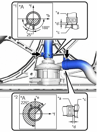
| *A | for 8ZR-FXE |
| *1 | Inlet Hybrid Water Pump Hose |
| *2 | Outlet No. 1 Hybrid Water Pump Hose |
| *a | Alignment Mark |
| *b | RH Side |
| *c | Rib |
| *d | 2 to 6 mm (0.0787 to 0.236 in.) |
| *e | Up |
| *f | Front of Vehicle |
Connect the outlet No. 1 hybrid water pump hose and inlet hybrid water pump hose to the inverter water pump with motor assembly and slide the 2 clips to secure them.
- NOTICE:
- ·
To prevent foreign matter from entering the inverter water pump with motor assembly and inverter cooling system, do not remove the pieces of cloth from the pipes and disconnected hoses until installation.
·Make sure to align the alignment marks of the hoses with the ribs of the inverter water pump with motor assembly.
·Do not apply excessive force to the hoses.
·If the inverter water pump with motor assembly has been struck or dropped, replace it.
·Make sure to connect the outlet No. 1 hybrid water pump hose and inlet hybrid water pump hose to the point where they contact the rib of the inverter water pump with motor assembly.
- HINT:
-
Make sure that the clips are positioned as shown in the illustration.
Temporarily install the inverter water pump with motor assembly to the fan shroud assembly with the 2 bolts.
Fully tighten the 2 bolts.
- Torque:
- 7.0 N*m (71 kgf*cm, 62 in.*lbf)
- NOTICE:
-
As overtightening the bolts may damage the fan shroud assembly, make sure to use a torque wrench.
Connect the inverter water pump with motor assembly connector.
- NOTICE:
-
If a dustproof cap is installed to the inverter water pump with motor assembly connector, do not remove it until the connector is to be connected.
2.ADD COOLANT (for Inverter)
3.INSPECT FOR COOLANT LEAK (for Inverter)
51410
4.INSTALL NO. 1 ENGINE UNDER COVER ASSEMBLY