DOOR LOCK REAR DOOR LOCK REMOVAL
CAUTION / NOTICE / HINT
The necessary procedures (adjustment, calibration, initialization, or registration) that must be performed after parts are removed and installed, or replaced during rear door lock with motor assembly removal/installation are shown below.
| Replaced Part or Performed Procedure | Necessary Procedure | Effect/Inoperative Function When Necessary Procedures are not Performed | Link |
|---|---|---|---|
·
Rear door glass sub-assembly ·
Rear door glass run ·
Rear door inner glass weatherstrip |
Initialize power window control system | ·
Auto up and down function ·
Jam protection function ·
Remote control function ·
Key-linked function ·
Wireless transmitter-linked function ·
Key-off operation function ·
Catch protection function ·
Window open warning function |
( 202304,999999,_59,_080745,_0600091,RM100000002BB3M,) 202304,999999,_59,_080745,_0600091,RM100000002BB3M,)
|
| Replaced Part or Performed Procedure | Necessary Procedure | Effect/Inoperative Function When Necessary Procedures are not Performed | Link |
|---|---|---|---|
·
Rear door glass sub-assembly ·
Rear door glass run ·
Rear door inner glass weatherstrip |
Initialize power window control system | ·
Auto up and down function ·
Jam protection function ·
Remote control function ·
Key-linked function ·
Wireless transmitter-linked function ·
Key-off operation function ·
Catch protection function ·
Window open warning function |
for NR Series Engine Initialization:(202304,999999,_59,_080745,_0600092,RM100000002BB4K,)
except NR Series Engine Registration:( 202304,999999,_59,_080745,_0600091,RM100000002BB3M,)
|
- NOTICE:
-
After the ignition switch is turned off, there may be a waiting time before disconnecting the negative (-) auxiliary battery terminal.
- HINT:
- ·
When the cable is disconnected / reconnected to the auxiliary battery terminal, systems temporarily stop operating. However, each system has a function that completes learning the first time the system is used.
-for HV Model:
Items for which learning is completed by driving the vehicle Effect/Inoperative Function When Necessary Procedures are not Performed Necessary Procedures Link Front Camera System Drive the vehicle straight ahead at 15 km/h (9 mph) or more for 1 second or more. ( 202304,999999,_95,_139716,_0584193,RM1000000029F4C,)
-for Gasoline Model:
Items for which learning is completed by driving the vehicle Effect/Inoperative Function When Necessary Procedures are not Performed Necessary Procedures Link Stop and Start System Idle the engine for approximately 5 to 60 minutes or drive the vehicle until stop and start control is permitted ( 201906,999999,_51,_080774,_0393362,RM100000001HXHC,)
Pre-collision System Perform steering sensor zero point calibration ( 202304,999999,_95,_139716,_0601175,RM100000002BFOE,)
Lane Tracing Assist System Front Camera System Drive the vehicle straight ahead at 15 km/h (9 mph) or more for 1 second or more. ( 202304,999999,_95,_139716,_0584193,RM1000000029F4C,)
·Use the same procedure for the RH side and LH side.
·The following procedure is for the LH side.
PROCEDURE

 1. PRECAUTION
- NOTICE:
-
After turning the ignition switch (for Gasoline Model) or power switch (for HV Model) off, waiting time may be required before disconnecting the cable from the negative (-) auxiliary battery terminal. Therefore, make sure to read the disconnecting the cable from the negative (-) auxiliary battery terminal notices before proceeding with work.
64490
2.REMOVE LUGGAGE COMPARTMENT SIDE TRAY ASSEMBLY (for M20F-FXS, M20G-FXS)
3.DISCONNECT CABLE FROM NEGATIVE AUXILIARY BATTERY TERMINAL
for NR Series: Click hereGeneral>MAINTENANCE>NR Series BATTERY>REMOVAL202304,999999,_V1,_080956,_0392375,RM100000002BCCL_05_0005,
for 8ZR-FXE: Click hereGeneral>MAINTENANCE>8ZR-FXE AUXILIARY BATTERY>REMOVAL202304,999999,_V1,_080956,_0392376,RM100000002ACL7_01_0028,
for M15B-FKS: Click hereGeneral>MAINTENANCE>M15B-FKS BATTERY>REMOVAL202304,999999,_V1,_080956,_0453685,RM100000002ACNG_05_0005,
for M15C-FKS: Click hereGeneral>MAINTENANCE>M15C-FKS BATTERY>REMOVAL202304,999999,_V1,_080956,_0453686,RM100000002ACNH_05_0005,
for M20A-FKS: Click hereGeneral>MAINTENANCE>M20A-FKS BATTERY>REMOVAL202304,999999,_V1,_080956,_0470107,RM100000002ACOV_05_0005,
for M20E-FKS: Click hereGeneral>MAINTENANCE>M20E-FKS BATTERY>REMOVAL202304,999999,_V1,_080956,_0474497,RM100000002ACOX_05_0005,
for M20C-FKS: Click hereGeneral>MAINTENANCE>M20C-FKS BATTERY>REMOVAL202304,999999,_V1,_080956,_0484846,RM100000002ACOW_05_0005,
M20F-FXS, M20G-FXS: Click hereGeneral>MAINTENANCE>M20F-FXS, M20G-FXS AUXILIARY BATTERY>REMOVAL202307,999999,_V1,_080956,_0611807,RM100000002CK9K_01_0013,
69284G
4.REMOVE REAR DOOR INSIDE HANDLE BEZEL PLUG
5.REMOVE REAR POWER WINDOW REGULATOR SWITCH ASSEMBLY WITH REAR DOOR UPPER ARMREST BASE PANEL
67604
6.REMOVE REAR DOOR TRIM BOARD SUB-ASSEMBLY
86160B
7.REMOVE REAR SPEAKER ASSEMBLY
67674A
8.REMOVE REAR DOOR FRAME GARNISH
67848A
9.REMOVE REAR DOOR NO. 1 VENT SEAL
67858A
10.REMOVE REAR DOOR PANEL PROTECTOR
67842E
11.REMOVE REAR DOOR SERVICE HOLE COVER
68152C
12.REMOVE REAR DOOR GLASS RUN
67872
13.DISCONNECT REAR DOOR WEATHERSTRIP
Disconnect the rear door weatherstrip until the screw of the rear door window division bar sub-assembly is visible.
67408H
14.REMOVE REAR DOOR WINDOW DIVISION BAR SUB-ASSEMBLY
68104
15.REMOVE REAR DOOR GLASS SUB-ASSEMBLY
69060A
16.REMOVE REAR DOOR LOCK WITH MOTOR ASSEMBLY
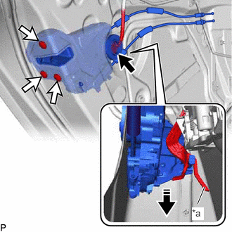
| *a | Release Plate |

|
Remove in this Direction |
Disconnect the connector.
Using a T30 "TORX" socket wrench, remove the 3 screws.
Move the rear door lock with motor assembly downward as shown in the illustration to disconnect it from the release plate of the rear door outside handle frame sub-assembly, and remove the rear door lock with motor assembly.
When reusing the rear door lock with motor assembly:
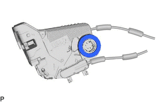
Remove the door lock wiring harness seal from the rear door lock with motor assembly.
69038A
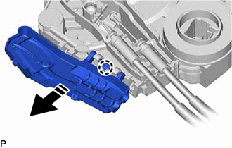
17.REMOVE REAR DOOR LOCK COVER SUB-ASSEMBLY (w/ Cover)
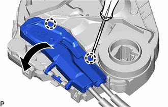
Using a screwdriver, disengage the 2 claws as shown in the illustration.
|
|
Remove in this Direction |
Disengage the claw to remove the rear door lock cover sub-assembly as shown in the illustration.
69740E
18.REMOVE REAR DOOR LOCK OPEN LEVER REMOTE CONTROL CABLE
w/o Cover:
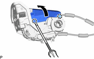
Using a screwdriver, disengage the 2 claws and open the cover as shown in the illustration.
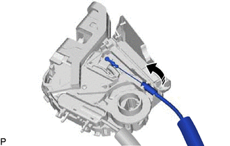
|
|
Remove in this Direction |
Remove the rear door lock open lever remote control cable as shown in the illustration.
w/ Cover:
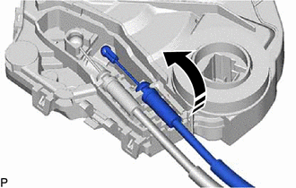
|
|
Remove in this Direction |
Remove the rear door inside lock/unlock knob locking cable as shown in the illustration.
69780E
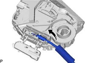
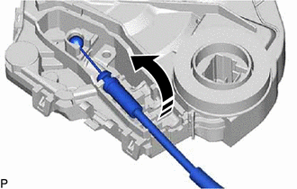
19.REMOVE REAR DOOR INSIDE LOCK/UNLOCK KNOB LOCKING CABLE
w/o Cover:
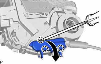
Using a screwdriver, disengage the 3 claws and open the cover as shown in the illustration.
|
|
Remove in this Direction |
Remove the rear door inside lock/unlock knob locking cable as shown in the illustration.
w/ Cover:
|
|
Remove in this Direction |
Remove the rear door inside lock/unlock knob locking cable as shown in the illustration.