DOOR / HATCH FRONT DOOR REASSEMBLY
CAUTION / NOTICE / HINT
- HINT:
- ·
Use the same procedure for the RH side and LH side.
·The following procedure is for the LH side.
PROCEDURE

 1. PRECAUTION
- NOTICE:
-
After turning the ignition switch (for Gasoline Model) or power switch (for HV Model) off, waiting time may be required before disconnecting the cable from the negative (-) auxiliary battery terminal. Therefore, make sure to read the disconnecting the cable from the negative (-) auxiliary battery terminal notices before proceeding with work.
75754A
2.INSTALL FRONT DOOR UPPER WINDOW FRAME MOULDING
75752A
3.INSTALL FRONT DOOR WINDOW FRAME MOULDING (FRONT PILLAR SIDE)
67852D
4.INSTALL FRONT DOOR REAR OUTSIDE SEAL
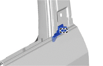
Engage the guide to install the front door rear outside seal.
75756D
5.INSTALL FRONT DOOR WINDOW FRAME MOULDING (CENTER PILLAR SIDE)
75792
6.INSTALL DOOR WINDOW FRAME MOULDING CLIP
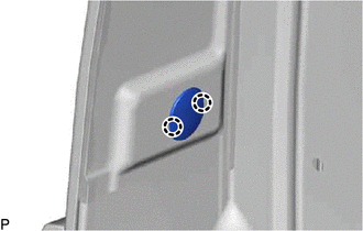
Engage the 2 claws to install the door window frame moulding clip.
67811
7.INSTALL FRONT DOOR SILENCER PAD
Clean the front door panel surface.
Remove any remaining butyl tape from the front door panel.
Wipe off any tape adhesive residue with cleaner.
Remove the release paper from 2 new front door silencer pads.
- HINT:
-
After removing the release paper, keep the exposed adhesive free from foreign matter.
Install the 2 front door silencer pads as shown in the illustration.
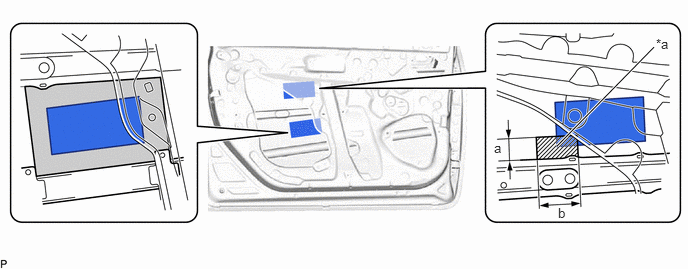
| *a | Corner of Front Door Silencer Pad | - | - |

|
Installation Area of Corner of Front Door Silencer Pad | 
|
Front Door Silencer Pad Installation Area |
| Area | Measurement | Area | Measurement |
|---|---|---|---|
| a | 30 mm (1.18 in.) | b | 56.1 mm (2.209 in.) |
8.INSTALL FRONT DOOR DUST PROOF SEAL
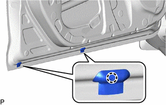
Engage the 2 claws to install 2 new front door dust proof seals.
75720
9.INSTALL FRONT DOOR BELT MOULDING
67001A
10.INSTALL FRONT DOOR PANEL CUSHION
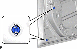
Engage the 4 claws to install 2 new front door panel cushions.
69312
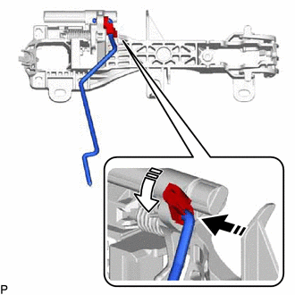
11.INSTALL FRONT DOOR LOCK OPEN ROD

|
Install in this Direction (1) |

|
Install in this Direction (2) |
Install the front door lock open rod as shown in the illustration.
69202A
12.INSTALL FRONT DOOR OUTSIDE HANDLE FRAME SUB-ASSEMBLY
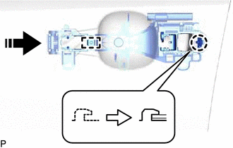
Apply MP grease to the sliding parts on the front door outside handle frame sub-assembly.
|
|
Install in this Direction |
Engage the guide and claw as shown in the illustration.
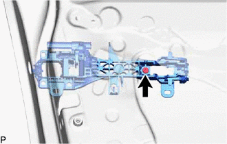
Using a T30 "TORX" socket wrench, install the front door outside handle frame sub-assembly with the screw.
- Torque:
- 4.0 N*m (41 kgf*cm, 35 in.*lbf)
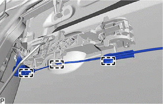
Engage the 3 clamps.
69040A
13.INSTALL FRONT DOOR LOCK WITH MOTOR ASSEMBLY
69242E
14.INSTALL FRONT DOOR REAR OUTSIDE HANDLE PAD
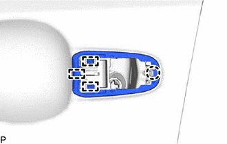
Engage the 3 guides and claw to install the front door rear outside handle pad.
69241H
15.INSTALL FRONT DOOR FRONT OUTSIDE HANDLE PAD

Engage the guide and 2 claws to install the front door front outside handle pad.
69217E
16.INSTALL FRONT DOOR OUTSIDE HANDLE COVER (for Front Passenger Side)
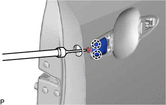
Engage the 2 claws.
Using a T30 "TORX" socket wrench, install the front door outside handle cover with the screw.
- Torque:
- 4.0 N*m (41 kgf*cm, 35 in.*lbf)
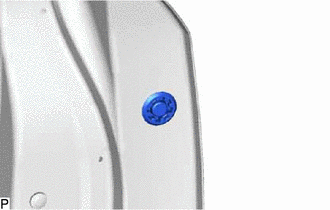
Install the hole plug.
17.INSTALL FRONT DOOR LOCK CYLINDER ASSEMBLY (for Driver Side)
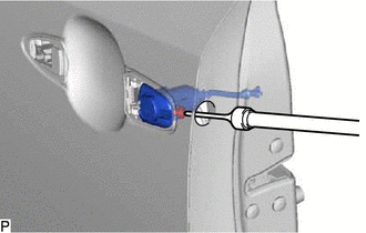
Using a T30 "TORX" socket wrench, install the front door lock cylinder assembly with the screw.
- Torque:
- 4.0 N*m (41 kgf*cm, 35 in.*lbf)
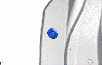
Install the hole plug.
69220
18.INSTALL FRONT DOOR OUTSIDE HANDLE ASSEMBLY
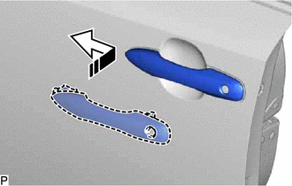
|
|
Install in this Direction |
Insert the front end of the front door outside handle assembly into the front door outside handle frame sub-assembly.
Insert the rear end of the front door outside handle assembly into the front door outside handle frame sub-assembly, then slide the front door outside handle assembly toward the front of the vehicle to install it.
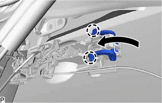
Move the lever as shown in the illustration and engage the 2 claws to secure the front door outside handle assembly.
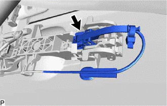
Connect the connector.
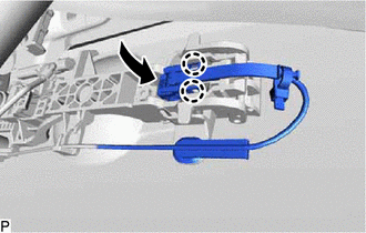
Engage the 2 claws as shown in the illustration.
67404F
19.INSTALL FRONT DOOR REAR LOWER FRAME SUB-ASSEMBLY
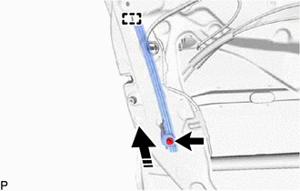
|
|
Install in this Direction |
Engage the guide as shown in the illustration.
Install the front door rear lower frame sub-assembly with the bolt.
- Torque:
- 8.5 N*m (87 kgf*cm, 75 in.*lbf)
68216
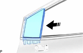
20.INSTALL FRONT DOOR FIX WINDOW WEATHERSTRIP
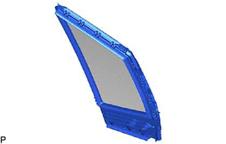
Install the front door fix window weatherstrip from the front door fix window glass.
|
|
Install in this Direction |
Install the front door fix window weatherstrip with front door fix window glass as shown in the illustration.
67402F
21.INSTALL FRONT DOOR FRONT LOWER FRAME SUB-ASSEMBLY
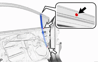
Install the screw.
Install the front door front lower frame sub-assembly with the 2 bolts.
- Torque:
- 8.5 N*m (87 kgf*cm, 75 in.*lbf)
68151D
22.INSTALL FRONT DOOR GLASS RUN
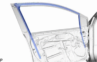
Install the front door glass run.
23.INSTALL FRONT DOOR WINDOW REGULATOR ASSEMBLY
Apply MP grease to the sliding parts of the front door window regulator assembly.
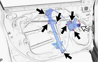
Install the front door window regulator assembly with the 7 nuts.
- Torque:
- 8.0 N*m (82 kgf*cm, 71 in.*lbf)
Connect the connector.
68102
24.INSTALL FRONT DOOR GLASS SUB-ASSEMBLY
for Driver Side:
Connect the multiplex network master switch assembly.
for Front Passenger Side:
Connect the power window regulator switch assembly.
Connect the cable to the negative (-) auxiliary battery terminal.
Turn the ignition switch (for Gasoline Model) or power switch (for HV Model) on (IG).
Move the front door window regulator assembly so that the door glass bolt holes can be seen.
Turn the ignition switch (for Gasoline Model) or power switch (for HV Model) off.
Disconnect the cable from the negative (-) auxiliary battery terminal.
for Driver Side:
Disconnect the multiplex network master switch assembly.
for Front Passenger Side:
Disconnect the power window regulator switch assembly.
|
|
Install in this Direction (1) |
|
|
Install in this Direction (2) |
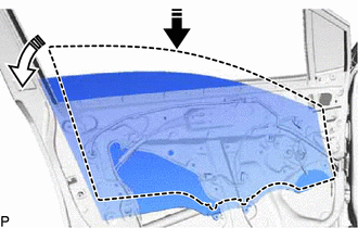
Insert the front door glass sub-assembly into the front door panel along the front door glass run as shown in the illustration.
- NOTICE:
-
Do not damage the front door glass sub-assembly.
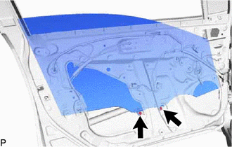
Install the front door glass sub-assembly with the 2 bolts.
- Torque:
- 8.0 N*m (82 kgf*cm, 71 in.*lbf)
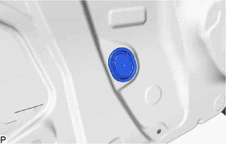
Install the hole plug.
67862
25.INSTALL FRONT DOOR WEATHERSTRIP
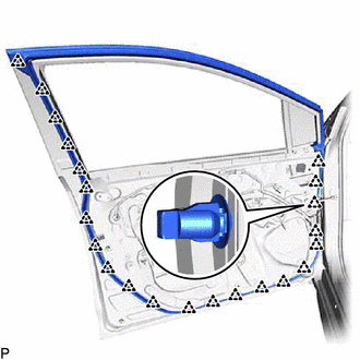
Engage the 22 clips and install the front door weatherstrip.
68610
26.INSTALL FRONT DOOR CHECK ASSEMBLY
Clean the bolt (B) hole on the vehicle body.
Clean the threads of the bolt (B).
Apply adhesive to the threads of the bolt (B).
- Adhesive:
Toyota Genuine Adhesive 1324, Three Bond 1324 or equivalent
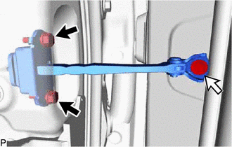

|
Bolt (A) |

|
Bolt (B) |
Install the front door check assembly with the 2 bolts (A) and bolt (B).
- Torque:
- Bolt (A) : 5.5 N*m (56 kgf*cm, 49 in.*lbf)
- Bolt (B) : 30 N*m (306 kgf*cm, 22 ft.*lbf)
67832
27.INSTALL FRONT DOOR SERVICE HOLE COVER
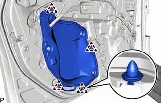
Engage the 4 clips to install the front door service hole cover.
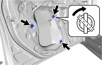
Insert the 3 front door weatherstrip clips and turn them 45 degrees as shown in the illustration to install them.
8983AA
28.INSTALL SIDE AIRBAG PRESSURE SENSOR
29.INSTALL OUTER REAR VIEW MIRROR ASSEMBLY WITH COVER
87964
30.INSTALL OUTER MIRROR INSTALL HOLE COVER
86160
31.INSTALL FRONT NO. 1 SPEAKER ASSEMBLY
67836C
32.INSTALL NO. 3 FRONT DOOR SERVICE HOLE COVER
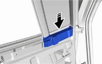
|
|
Install in this Direction |
Install the No. 3 front door service hole cover as shown in the illustration.
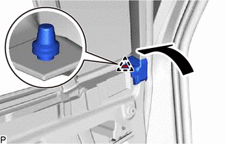
Engage the clip and connect the front door weatherstrip as shown in the illustration.
67838D
33.INSTALL FRONT DOOR VENT SEAL
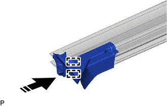
|
|
Install in this Direction |
Engage the 2 guides to install the front door vent seal to the front door inner glass weatherstrip as shown in the illustration.
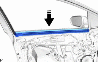
|
|
Install in this Direction |
Install the front door inner glass weatherstrip with front door vent seal as shown in the illustration.
67664C
34.INSTALL DOOR UPPER FRAME GARNISH
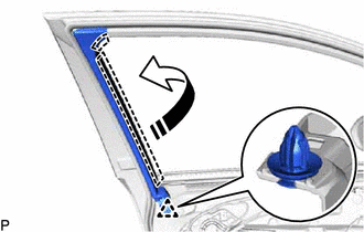
|
|
Install in this Direction |
Engage the 2 guides as shown in the illustration.
Engage the clip to install the door upper frame garnish.
69206B
35.INSTALL FRONT DOOR INSIDE HANDLE SUB-ASSEMBLY

Engage the 3 claws to install the front door inside handle sub-assembly.
67602
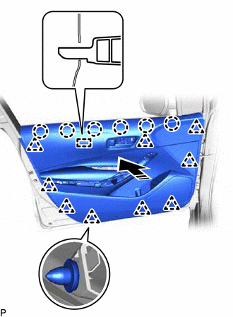
36.INSTALL FRONT DOOR TRIM BOARD SUB-ASSEMBLY
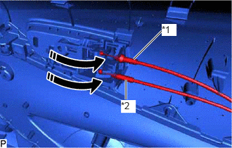
| *1 | Front Door Inside Lock/Unlock Knob Locking Cable |
| *2 | Front Door Lock Open Lever Remote Control Cable |
|
|
Install in this Direction |
Connect the front door lock open lever remote control cable and front door inside lock/unlock knob locking cable to the front door inside handle sub-assembly as shown in the illustration.
|
|
Install in this Direction |
Engage the guide, 6 claws and 9 clips as shown in the illustration.
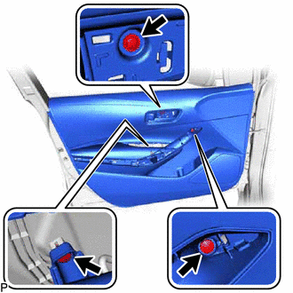
Install the front door trim board sub-assembly with the 3 screws.
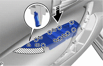
37.INSTALL MULTIPLEX NETWORK MASTER SWITCH ASSEMBLY WITH FRONT DOOR UPPER ARMREST BASE PANEL (for Driver Side)
Connect each connector.
|
|
Install in this Direction |
Engage the 5 guides, 8 claws and clip to install the multiplex network master switch assembly with front door upper armrest base panel as shown in the illustration.
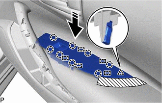
38.INSTALL POWER WINDOW REGULATOR SWITCH ASSEMBLY WITH FRONT DOOR UPPER ARMREST BASE PANEL (for Front Passenger Side)
Connect the connector.
|
|
Install in this Direction |
Engage the 5 guides, 8 claws and clip to install the power window regulator switch assembly with front door upper armrest base panel as shown in the illustration.
74640E
39.INSTALL FRONT DOOR ASSIST GRIP ASSEMBLY
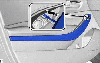
|
|
Install in this Direction |
Engage the claw as shown in the illustration.
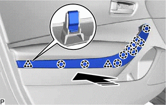
|
|
Install in this Direction |
Engage the 2 clips and 10 claws to install the front door assist grip assembly as shown in the illustration.
69284F
40.INSTALL FRONT DOOR INSIDE HANDLE BEZEL PLUG
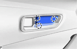
Engage the 3 claws to install the front door inside handle bezel plug.
41.CONNECT CABLE TO NEGATIVE AUXILIARY BATTERY TERMINAL
for NR Series:
for 8ZR-FXE:
for M15B-FKS:
for M15C-FKS:
for M20A-FKS:
for M20C-FKS:
for M20E-FKS:
for M20F-FXS, M20G-FXS:
64490
42.INSTALL LUGGAGE COMPARTMENT SIDE TRAY ASSEMBLY (for M20F-FXS, M20G-FXS)
43. INITIALIZE POWER WINDOW CONTROL SYSTEM
for NR Series Engine:
except NR Series Engine:
44.INSPECT POWER WINDOW OPERATION
for NR Series Engine:
except NR Series Engine:
45.INSPECT SRS WARNING LIGHT
except NR Series Engine:
for NR Series Engine: