8ZR-FXE ENGINE MECHANICAL CYLINDER BLOCK DISASSEMBLY
CAUTION / NOTICE / HINT
The necessary procedures (adjustment, calibration, initialization, or registration) that must be performed after parts are removed and installed, or replaced during engine unit removal/installation are shown below.
| Replaced Part or Performed Procedure | Necessary Procedure | Effect/Inoperative Function when Necessary Procedure not Performed | Link |
|---|---|---|---|
|
*: The vehicle height changes because of tire replacement. |
|||
| Replacement of ECM | Vehicle Identification Number (VIN) or frame number registration | DTC stored | ( 202304,999999,_51,_080778,_0393982,RM100000002BDLH,) 202304,999999,_51,_080778,_0393982,RM100000002BDLH,)
|
| ECU configuration | - | (202304,999999,_V1,_143216,_0598316,RM100000002B3MK,)
|
|
| Update ECU security key | Vehicle Control History (RoB) are stored | (202304,999999,_V1,_143216,_0598316,RM100000002B3ML,)
|
|
| Perform Total Short Trip Estimate Registration | - | (202304,999999,_51,_080778,_0393982,RM100000002BDLH,)
|
|
| Replacement of inverter with converter assembly | ECU configuration | - | (202304,999999,_V1,_143216,_0598316,RM100000002B3MK,)
|
| Resolver learning | ·
DTCs are stored ·
Slight vibration at a vehicle speed of 5 km/h (3 mph) or less ·
Shock or vibration during acceleration |
(202304,999999,_51,_080773,_0600292,RM100000002BBW3,)
|
|
·
Replacement of throttle body assembly ·
Replacement of cylinder head sub-assembly ·
Replacement of camshaft (for intake or exhaust camshaft) ·
Replacement of camshaft timing gear assembly ·
Replacement of piston or piston ring ·
Replacement of fuel injector assembly ·
Replacement of spark plug ·
Replacement of ignition coil assembly ·
Replacement of EGR valve assembly ·
Gas leak from exhaust system is repaired ·
Replacement of knock control sensor |
Inspection after repair | ·
Poor idle, etc. ·
Engine start function, etc. |
(202304,999999,_51,_080778,_0393982,RM100000002BDLI,)
|
| Replacement of hybrid vehicle transaxle assembly | ·
Resolver learning ·
Initialize resolver |
·
DTCs are stored ·
Slight vibration at a vehicle speed of 5 km/h (3 mph) or less |
(202304,999999,_51,_080773,_0600292,RM100000002BBW3,)
|
·
Tires ·
Suspension parts |
Rear television camera assembly optical axis (Back camera position setting)* | Parking Assist Monitor System | (202304,999999,_56,_080754,_0596561,RM100000002AX0C,)
|
| Parking assist ECU initialization | Panoramic View Monitor System | (202307,999999,_56,_080754,_0612151,RM100000002CL9H,)
|
|
| Front wheel alignment adjustment | 1.
Perform "Reset Memory" 2.
Perform "Calibration" |
·
DTCs are stored ·
ABS warning light illuminates ·
Brake system warning light (yellow indicator) illuminates ·
Slip indicator light illuminates ·
Electronically controlled brake system disabled or malfunctions |
(202304,999999,_54,_080770,_0392591,RM100000002B671,)
|
- HINT:
-
When the cable is disconnected / reconnected to the auxiliary battery terminal, systems temporarily stop operating. However, each system has a function that completes learning the first time the system is used.
Learning completes when vehicle is driven Effect/Inoperative Function when Necessary Procedure not Performed Necessary Procedure Link Front Camera System Drive the vehicle straight ahead at 15 km/h (9 mph) or more for 1 second or more. ( 202304,999999,_95,_139716,_0584193,RM1000000029F4C,)
PROCEDURE

 12211
1.REMOVE NO. 1 VENTILATION CASE
12211
1.REMOVE NO. 1 VENTILATION CASE
- HINT:
-
There are 2 installation types for the No. 1 ventilation case.
-
Depending on the installation type, the number of bolts, nuts and stud bolts used will vary.
Type A:
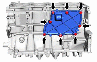
Remove the 6 bolts and 2 nuts.
Type B:
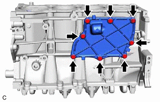
Remove the 8 bolts.
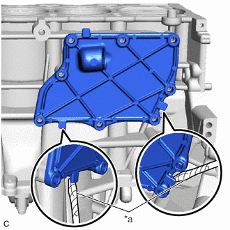
| *a | Protective Tape |
Remove the No. 1 ventilation case by prying between the No. 1 ventilation case and cylinder block sub-assembly with a screwdriver with its tip wrapped with protective tape.
- NOTICE:
-
Be careful not to damage the contact surfaces of the cylinder block sub-assembly and No. 1 ventilation case.
2.REMOVE PISTON SUB-ASSEMBLY WITH CONNECTING ROD
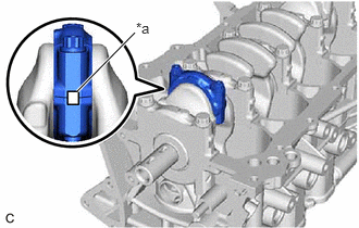
| *a | Paint Mark |
Place a paint mark across each corresponding connecting rod and connecting rod bearing cap.
- HINT:
-
The paint marks are used to ensure that the same parts are installed in the same combination to their original locations.
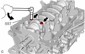
Using SST, remove the 8 connecting rod bolts from the connecting rod bearing caps.
- SST
- 09205-16011
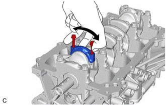
Using the 2 removed connecting rod bolts, remove the 4 connecting rod caps with connecting rod bearings by wiggling each connecting rod cap left and right.
- HINT:
-
Keep the connecting rod bearing installed to the connecting rod cap.
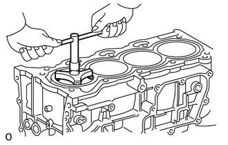
Using a ridge reamer, scrape off any carbon on the top of the cylinder.
Push out the 4 pistons with 4 connecting rods and 4 connecting rod bearings through the top of the cylinder block sub-assembly.
- HINT:
- ·
Keep the connecting rod bearings, connecting rods and connecting rod caps together.
·Arrange the removed parts in such a way that they can be reinstalled to their original locations.
13041
3.REMOVE CONNECTING ROD BEARING
Remove the 8 connecting rod bearings from the 4 connecting rods and 4 connecting rod caps.
- HINT:
-
Arrange the removed parts in such a way that they can be reinstalled to their original locations.
13411
4.REMOVE CRANKSHAFT
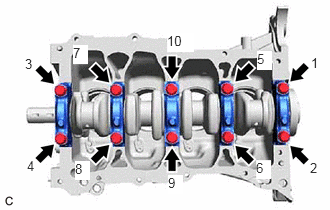
Uniformly loosen and remove the 10 crankshaft bearing cap set bolts in several steps in the order shown in the illustration.
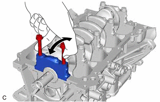
Using the 2 removed crankshaft bearing cap set bolts, remove the 5 crankshaft bearing caps from the cylinder block sub-assembly by wiggling each crankshaft bearing cap back and forth.
- HINT:
-
Arrange the removed parts in such a way that they can be reinstalled to their original locations.
Remove the crankshaft from the cylinder block sub-assembly.
11711
5.REMOVE CRANKSHAFT BEARING
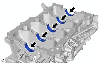
Remove the 5 upper crankshaft bearings from the cylinder block sub-assembly.
- HINT:
-
Arrange the removed parts in such a way that they can be reinstalled to their original locations.
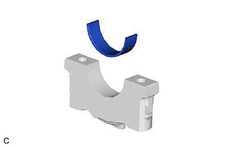
Remove the 5 lower crankshaft bearings from the 5 crankshaft bearing caps.
- HINT:
-
Arrange the removed parts in such a way that they can be reinstalled to their original locations.
11791
6.REMOVE UPPER CRANKSHAFT THRUST WASHER
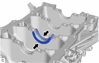
Remove the 2 upper crankshaft thrust washers from the cylinder block sub-assembly.
13011
7.REMOVE PISTON RING SET
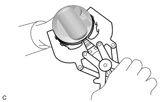
Using a piston ring expander, remove the No. 1 compression ring and No. 2 compression ring from the piston.
Remove the oil ring expander, upper side rail and lower side rail from the piston by hand.
- HINT:
-
Arrange the removed parts in such a way that they can be reinstalled to their original locations.
13101
8.REMOVE PISTON
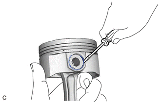
Using a screwdriver, pry out the piston pin hole snap ring from the piston.
- NOTICE:
- ·
Do not remove the piston pin hole snap ring (rear side) unless it is being replaced.
·Be careful not to damage the piston when removing the piston pin hole snap ring (rear side).

Gradually heat the piston to approximately 80°C (176°F).
- CAUTION:
-
Be sure to wear protective gloves.
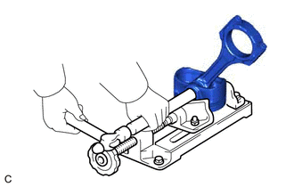
Using a brass bar and a hammer, lightly tap out the piston pin and remove the connecting rod.
- HINT:
- ·
The piston and piston pin are a matched set.
·Arrange the removed parts in such a way that they can be reinstalled to their original locations.
15708
9.REMOVE NO. 1 OIL NOZZLE SUB-ASSEMBLY
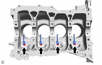
Using a 5 mm hexagon socket wrench, remove the 4 bolts and 4 No. 1 oil nozzle sub-assemblies from the cylinder block sub-assembly.