REAR SUSPENSION REAR TRAILING ARM(w/ Electric Parking Brake) REMOVAL
CAUTION / NOTICE / HINT
The necessary procedures (adjustment, calibration, initialization, or registration) that must be performed after parts are removed and installed, or replaced during rear trailing arm assembly removal/installation are shown below.
| Replaced Part or Performed Procedure | Necessary Procedure | Effect/Inoperative Function when Necessary Procedure not Performed | Link |
|---|---|---|---|
|
*: The vehicle height changes because of tire replacement. |
|||
| Rear wheel alignment adjustment | 1.
Perform "Reset Memory" 2.
Perform "Calibration" |
·
DTCs are stored ·
ABS warning light illuminates ·
Brake system warning light (yellow indicator) illuminates ·
Slip indicator light illuminates ·
Electronically controlled brake system disabled or malfunctions |
( 202304,999999,_54,_080770,_0392591,RM100000002B671,) 202304,999999,_54,_080770,_0392591,RM100000002B671,)
|
·
Tires ·
Suspension parts |
Rear television camera assembly optical axis (Back camera position setting)* | Parking Assist Monitor System | (202304,999999,_56,_080754,_0596561,RM100000002AX0C,)
|
| Parking assist ECU initialization | Panoramic View Monitor System | (202307,999999,_56,_080754,_0612151,RM100000002CL9H,)
|
|
| Replaced Part or Performed Procedure | Necessary Procedure | Effect/Inoperative Function when Necessary Procedure not Performed | Link |
|---|---|---|---|
|
*: The vehicle height changes because of tire replacement. |
|||
| Rear wheel alignment adjustment | for NR Series
·
Perform "Reset Memory" ·
Perform acceleration sensor zero point calibration and store system information memorization |
·
VSC is disabled or malfunctions ·
DTCs are output ·
Slip indicator light illuminates ·
ABS warning light illuminates |
(202304,999999,_54,_080770,_0599814,RM100000002BA8F,)
|
except NR Series
·
Perform "Reset Memory" ·
Perform "Calibration" |
·
VSC is disabled or malfunctions ·
DTCs are output ·
Slip indicator light illuminates ·
ABS warning light illuminates |
(202304,999999,_54,_080770,_0599811,RM100000002B9XU,)
|
|
·
Tires ·
Suspension parts |
Rear television camera assembly optical axis (Back camera position setting)* | Parking Assist Monitor System | (202304,999999,_56,_080754,_0596561,RM100000002AX0C,)
|
CAUTION / NOTICE / HINT
- HINT:
- ·
Use the same procedure for the RH side and LH side.
·The following procedure is for the LH side.
PROCEDURE

 1.REMOVE REAR WHEEL
57628E
2.REMOVE REAR FLOOR SIDE MEMBER COVER LH (for HV Model)
57627G
3.REMOVE REAR FLOOR SIDE MEMBER COVER RH (for HV Model)
57628E
4.REMOVE REAR FLOOR SIDE MEMBER COVER LH (for Gasoline Model)
57627G
5.REMOVE REAR FLOOR SIDE MEMBER COVER RH (for Gasoline Model)
890C0A
6.SEPARATE NO. 2 PARKING BRAKE WIRE ASSEMBLY
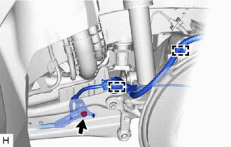
Disengage the 2 clamps.
Remove the nut and separate the No. 2 parking brake wire assembly from the rear trailing arm assembly.
48840A
7.REMOVE REAR STABILIZER LINK ASSEMBLY (w/ Stabilizer Bar)
48780E
8.REMOVE REAR TRAILING ARM ASSEMBLY
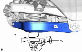
| *a | Wooden Block |
| *b | Transmission Jack |
Using a transmission jack and a wooden block, support the rear No. 2 suspension arm assembly.
- NOTICE:
- ·
When jacking up the rear No. 2 suspension arm assembly, be sure to jack it up slowly.
·Make sure to perform this operation with the vehicle kept as low as possible.
w/o Stabilizer Bar:
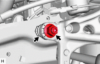
Remove the bolt and nut from the rear axle carrier sub-assembly and rear trailing arm assembly.
- NOTICE:
-
Because the bolt has its own stopper, do not turn the bolt. Loosen the nut with the bolt secured.
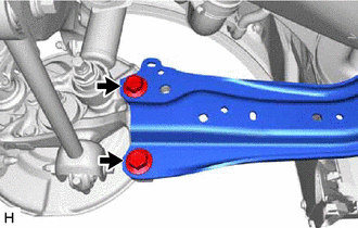
Remove the 2 bolts and separate the rear trailing arm assembly from the rear axle carrier sub-assembly.
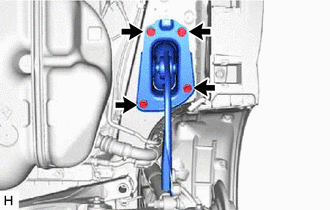
Remove the 4 bolts and rear trailing arm assembly.
48738
9.REMOVE REAR SUSPENSION ARM COVER
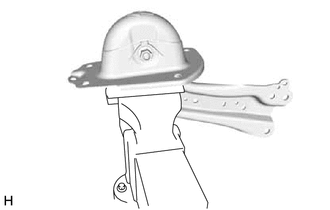
Secure the rear trailing arm assembly in a vise using aluminum plates.
- NOTICE:
-
Do not overtighten the vise.
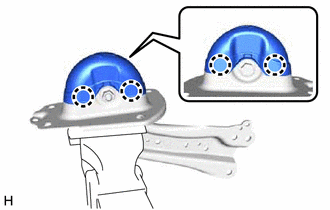
Disengage the 4 claws and remove the rear suspension arm cover.
48727
10.REMOVE REAR SUSPENSION ARM BRACKET
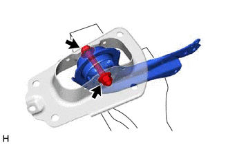
Remove the bolt, nut and rear suspension arm bracket from the rear trailing arm assembly.