FRONT SUSPENSION FRONT SHOCK ABSORBER REMOVAL
CAUTION / NOTICE / HINT
The necessary procedures (adjustment, calibration, initialization, or registration) that must be performed after parts are removed and installed, or replaced during front shock absorber assembly removal/installation are shown below.
| Replaced Part or Performed Procedure | Necessary Procedure | Effect/Inoperative Function when Necessary Procedure not Performed | Link |
|---|---|---|---|
|
*: The vehicle height changes because of tire replacement. |
|||
| Front wheel alignment adjustment | 1.
Perform "Reset Memory" 2.
Perform "Calibration" |
·
DTCs are stored ·
ABS warning light illuminates ·
Brake system warning light (yellow indicator) illuminates ·
Slip indicator light illuminates ·
Electronically controlled brake system disabled or malfunctions |
( 202304,999999,_54,_080770,_0392591,RM100000002B671,) 202304,999999,_54,_080770,_0392591,RM100000002B671,)
|
·
Tires ·
Suspension parts |
Rear television camera assembly optical axis (Back camera position setting)* | Parking Assist Monitor System | (202304,999999,_56,_080754,_0596561,RM100000002AX0C,)
|
| Parking assist ECU initialization | Panoramic View Monitor System | (202307,999999,_56,_080754,_0612151,RM100000002CL9H,)
|
|
| Replaced Part or Performed Procedure | Necessary Procedure | Effect/Inoperative Function when Necessary Procedure not Performed | Link |
|---|---|---|---|
|
*: The vehicle height changes because of tire replacement. |
|||
| Front wheel alignment adjustment | for NR Series
·
Perform "Reset Memory" ·
Perform acceleration sensor zero point calibration and store system information memorization |
·
VSC is disabled or malfunctions ·
DTCs are output ·
Slip indicator light illuminates ·
ABS warning light illuminates |
(202304,999999,_54,_080770,_0599814,RM100000002BA8F,)
|
except NR Series
·
Perform "Reset Memory" ·
Perform "Calibration" |
·
VSC is disabled or malfunctions ·
DTCs are output ·
Slip indicator light illuminates ·
ABS warning light illuminates |
(202304,999999,_54,_080770,_0599811,RM100000002B9XU,)
|
|
·
Tires ·
Suspension parts |
Rear television camera assembly optical axis (Back camera position setting)* | Parking Assist Monitor System | (202304,999999,_56,_080754,_0596561,RM100000002AX0C,)
|
- HINT:
- ·
Use the same procedure for the RH side and LH side.
·The following procedure is for the LH side.
PROCEDURE

 1.REMOVE FRONT WHEEL
2.REMOVE WINDSHIELD WIPER MOTOR AND LINK ASSEMBLY
55737B
3.REMOVE NO. 1 HEATER AIR DUCT SPLASH SHIELD SEAL (w/ No. 1 Heater Air Duct Splash Shield Seal)
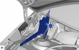
Disengage the claw and remove the No. 1 heater air duct splash shield seal from the outer cowl top panel sub-assembly.
55701J
4.REMOVE OUTER COWL TOP PANEL SUB-ASSEMBLY

Remove the 9 bolts, 4 nuts and outer cowl top panel sub-assembly.
48684B
5.REMOVE FRONT SUSPENSION SUPPORT DUST COVER
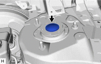
Remove the front suspension support dust cover from the front shock absorber assembly.
48609E
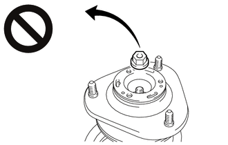
6.LOOSEN FRONT SUPPORT TO FRONT SHOCK ABSORBER NUT
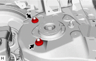
Temporarily install the 2 nuts to the front shock absorber assembly.
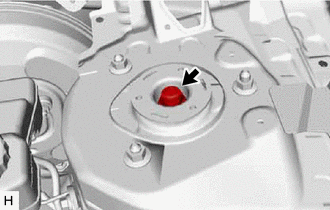
Loosen the front support to front shock absorber nut.
- CAUTION:
-
- ·
Only loosen the front support to front shock absorber nut if the front shock absorber with coil spring needs to be disassembled.
·Only loosen the front support to front shock absorber nut, do not remove it.
·If the front support to front shock absorber nut is removed with the front coil spring under tension, components of the front shock absorber with coil spring may fly off.
48810
7.SEPARATE FRONT STABILIZER LINK ASSEMBLY
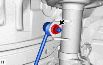
Remove the nut and separate the front stabilizer link assembly from the front shock absorber assembly.
- NOTICE:
-
Do not damage the boot of the ball joint.
- HINT:
-
If the ball joint turns together with the nut, use a 6 mm hexagon socket wrench to hold the stud bolt.
89543
8.SEPARATE FRONT SPEED SENSOR
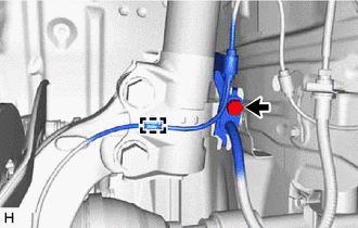
Remove the bolt, disengage the clamp and separate the front speed sensor and front flexible hose from the front shock absorber assembly.
- NOTICE:
-
Be sure to separate the front speed sensor and front flexible hose from the front shock absorber assembly completely.
9.REMOVE FRONT SHOCK ABSORBER WITH COIL SPRING
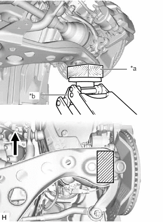
| *a | Wooden Block |
| *b | Jack |

|
Front of the Vehicle |

|
Wooden Block Placement Location |
Support the front lower No. 1 suspension arm sub-assembly using a jack and wooden block.
- NOTICE:
-
Keep the front lower No. 1 suspension arm sub-assembly supported until installation of the front shock absorber with coil spring is complete.
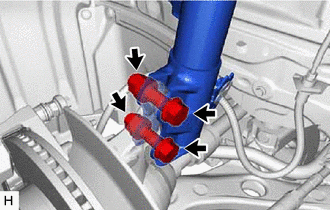
Remove the 2 bolts and 2 nuts, and separate the front shock absorber with coil spring (lower side) from the steering knuckle.
- NOTICE:
- ·
When removing the nuts, keep the bolts from rotating.
·Use wire or an equivalent tool to hang the separated steering knuckle.
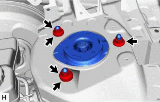
Remove the 3 nuts, 2 spacers and front shock absorber with coil spring.
48609E
10.REMOVE FRONT SUPPORT TO FRONT SHOCK ABSORBER NUT
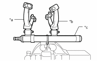
| *a | SST(09727-00051) |
| *b | SST(09727-00040) |
| *c | SST(09727-30022 (09727-00010, 09727-00031)) |
Secure SST in a vise.
- SST
- 09727-00051
09727-30022 (09727-00010, 09727-00031)
09727-00040
Attach the hooks of each SST arm across the diameter of the coil spring.
- CAUTION:
- ·
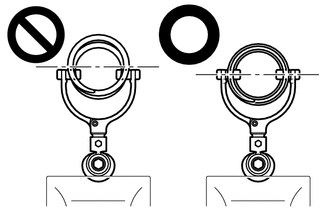
Make sure that the hooks are securely attached to the coil spring.
·If a hook disengages from the coil spring, the coil spring may fly out, resulting in injury.
·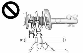
Make sure that the hooks of the upper and lower SST arms are attached to the coil spring so that the distance between the hooks is as large as possible.
·If a hook disengages from the coil spring, the coil spring may fly out, resulting in injury.
·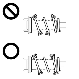
Make sure that the arms of SST are parallel and the number of coils between the arms is the same on each side.
·If a hook disengages from the coil spring, the coil spring may fly out, resulting in injury.
Install the stopper pins to the hooks of SST.
- CAUTION:
-
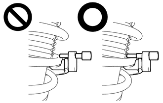
- ·
Make sure that the stopper pins are installed securely.
·If a hook disengages from the coil spring, the coil spring may fly out, resulting in injury.
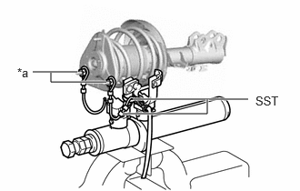
| *a | Vehicle Nut |
Install SST and 2 vehicle nuts to the upper support as shown in the illustration.
- SST
- 09727-30022 (09727-00090, 09727-00100)
Install SST as shown in the illustration.
- CAUTION:
-
The pin is not attached to one side, so be sure to hang the belt.
- SST
- 09727-00110
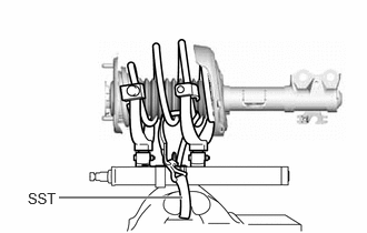
Using SST, compress the coil spring.
- CAUTION:
- ·
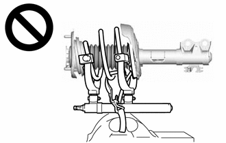
If the coil spring starts to bow out while using SST, stop immediately and reattach SST correctly.
·If a hook disengages from the coil spring, the coil spring may fly out, resulting in injury.
·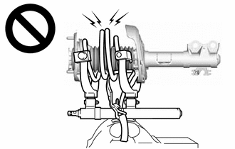
Do not compress the coil spring to the point where the coils touch each other.
·If a hook disengages from the coil spring, the coil spring may fly out, resulting in injury.
·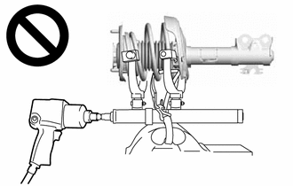
Do not use an impact wrench.
·If an impact wrench is used, the threads of SST may be damaged, or sudden compression of the coil spring may cause a hook to disengage and the coil spring to fly out, resulting in injury.
·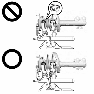
If a stopper pin touches the coil spring while using SST, remove the stopper pin and continue with the procedure.
·If a hook disengages from the coil spring, the coil spring may fly out, resulting in injury.
Check that the coil spring has become detached, and then remove the front support to front shock absorber nut.
- CAUTION:
-
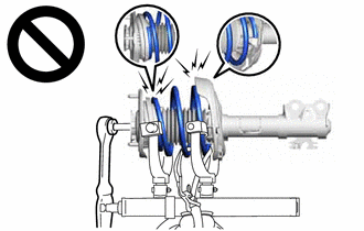
- ·
Do not remove the front support to front shock absorber nut while the coil spring is under tension.
·If the front support to front shock absorber nut is removed with the coil spring under tension, components of the front shock absorber with coil spring may fly off, resulting in injury.
11.REMOVE COLLAR
Remove the collar from the front shock absorber assembly.
48609
12.REMOVE FRONT SUSPENSION SUPPORT SUB-ASSEMBLY
Remove the front suspension support sub-assembly from the front shock absorber assembly.
13.REMOVE STRUT MOUNTING BEARING WITH DUST COVER
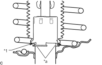
| *1 | Front No. 1 Shock Absorber Dust Cover |
| *a | Claw |
Disengage the end of the front No. 1 shock absorber dust cover from the claws of the front shock absorber assembly.
Remove the strut mounting bearing with dust cover from the front shock absorber assembly.
48157C
14.REMOVE FRONT UPPER COIL SPRING INSULATOR
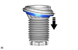

|
Remove in this direction |
Remove the front upper coil spring insulator from the strut mounting bearing.
48619A
15.REMOVE STRUT MOUNTING BEARING
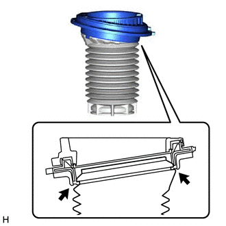
Disengage the top end of the front No. 1 shock absorber dust cover to remove the strut mounting bearing from the shock absorber dust cover.
48132
16.REMOVE FRONT COIL SPRING
Remove the front coil spring and SST.
- NOTICE:
-
Do not use an impact wrench. It will damage SST.
48331C
17.REMOVE FRONT SPRING BUMPER
Remove the front spring bumper from the front shock absorber assembly.
48158C
18.REMOVE FRONT LOWER COIL SPRING INSULATOR
Remove the front lower coil spring insulator from the front shock absorber assembly.
48520
19.REMOVE FRONT SHOCK ABSORBER ASSEMBLY