WIPER / WASHER WIPER AND WASHER SYSTEM(for HV Model) TERMINALS OF ECU
CHECK MAIN BODY ECU (MULTIPLEX NETWORK BODY ECU) AND POWER DISTRIBUTION BOX ASSEMBLY
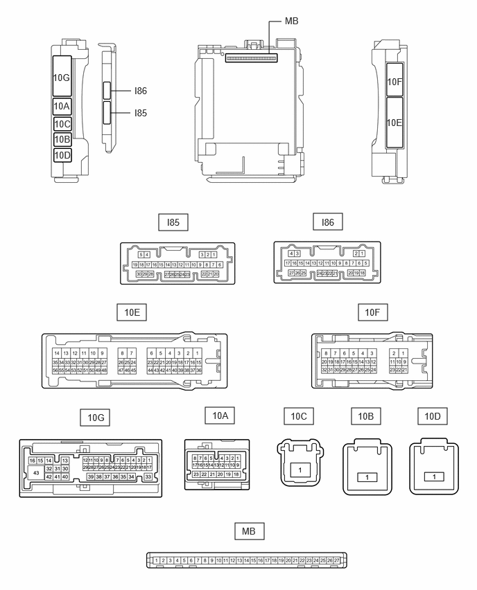
Disconnect the power distribution box assembly and main body ECU (multiplex network body ECU) connectors.
Measure the voltage and resistance according to the value(s) in the table below.
| Terminal No. (Symbol) | Wiring Color | Terminal Description | Condition | Specified Condition |
|---|---|---|---|---|
| 10F-1 - Body ground | W-B - Body ground | Ground | Always | Below 1 Ω |
| 10A-23 - Body ground | W - Body ground | Auxiliary battery power supply | Power switch off | 11 to 14 V |
| 10E-4 - Body ground | SB - Body ground*1
L - Body ground*2 B - Body ground*3 P - Body ground*4 |
Auxiliary battery power supply | Power switch off | 11 to 14 V |
| 10E-50 - Body ground | W - Body ground*1
Y - Body ground*3 |
Auxiliary battery power supply | Power switch off | 11 to 14 V |
*1: for TFTM Made (M20G-FXS, 8ZR-FXE w/o Smart Entry & Start System)
*3: for TFTM Made (8ZR-FXE/w Smart Entry & Start System)
*3: for GTMC Made (8ZR-FXE)
*4: for GTMC Made (M20F-FXS)
Connect the power distribution box assembly and main body ECU (multiplex network body ECU) connectors.
Measure the voltage and check for pulses according to the value(s) in the table below.
| Terminal No. (Symbol) | Wiring Color | Terminal Description | Condition | Specified Condition |
|---|---|---|---|---|
| 10A-9 (CXP1) - Body ground | P - Body ground*1
Y - Body ground*2 |
CXPI communication line | Power switch on (IG) | Pulse generation |
| Power switch off | Below 1 V | |||
| I85-6 (WPS) - Body ground | R - Body ground*1
P - Body ground*2 |
WIPER relay operation signal | Power switch on (IG) | 11 to 14 V |
| Less than approximately 60 seconds after power switch turned off | ||||
| Approximately 60 seconds or more after power switch turned off | Below 1 V |
*1: for TFTM Made, GTMC Made (M20F-FXS)
*2: except GTMC Made (M20F-FXS)
CHECK WINDSHIELD WIPER RELAY ASSEMBLY

Disconnect the A55 and A56 windshield wiper relay assembly connectors.
Measure the voltage and resistance according to the value(s) in the table below.
| Terminal No. (Symbol) | Wiring Color | Terminal Description | Condition | Specified Condition |
|---|---|---|---|---|
| A55-3 (E) - Body ground | W-B - Body ground | Ground | Always | Below 1 Ω |
| A55-5 (EWS) - Body ground | W-B - Body ground | Ground | Always | Below 1 Ω |
| A55-6 (IGWS) - Body ground | L - Body ground | Washer circuit IG power source | Power switch off | Below 1 V |
| Power switch on (IG) | 11 to 14 V | |||
| A55-8 (+B) - Body ground | B - Body ground | Power switch on (IG) signal (Power source circuit) | Power switch on (IG) | 11 to 14 V |
| Less than approximately 60 seconds after power switch turned off | ||||
| Approximately 60 seconds or more after power switch turned off | Below 1 V | |||
| A56-5 (ES) - Body ground | W-B - Body ground | Ground | Always | Below 1 Ω |
Connect the A55 and A56 windshield wiper relay assembly connectors.
Measure the voltage and check for pulses according to the value(s) in the table below.
| Terminal No. (Symbol) | Wiring Color | Terminal Description | Condition | Specified Condition |
|---|---|---|---|---|
| A55-1 (+WR) - Body ground | G - Body ground | Front washer operation signal | Power switch on (IG), front washer operating | 11 to 14 V |
| A55-2 (+1) - Body ground | R - Body ground | LO operation signal to windshield wiper motor assembly | Power switch on (IG), windshield wiper motor assembly operating in LO | 11 to 14 V |
| A55-4 (+2) - Body ground | W - Body ground | HI operation signal to windshield wiper motor assembly | Power switch on (IG), windshield wiper motor assembly operating in HI | 11 to 14 V |
| A56-3 (2S) - Body ground | V - Body ground*1
R - Body ground*2 |
Windshield wiper motor assembly HI operation signal | Windshield wiper motor assembly stopped | 4.5 to 5.5 V |
| Windshield wiper motor assembly operating in HI | Below 1 V | |||
| A56-4 (MPX1) - Body ground | P - Body ground*1
Y - Body ground*2 |
CXPI communication line | Power switch on (IG) | Pulse generation |
| Power switch off | Below 1 V | |||
| A56-6 (+SM) - Body ground | G - Body ground | Windshield wiper motor assembly position detection signal | Windshield wiper motor assembly in LO or HI operation | Below 1 V ←→ 11 to 14 V |
| Windshield wiper motor assembly stopped | Below 1 V |
*1: for TFTM Made, GTMC Made (M20F-FXS)
*2: except GTMC Made (M20F-FXS)