PA10/PB10 HYBRID TRANSMISSION / TRANSAXLE TRANSMISSION CONTROL CABLE ADJUSTMENT
PROCEDURE

 1.SECURE VEHICLE
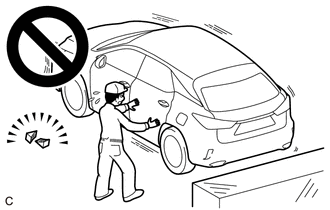
Fully apply the parking brake and chock a wheel.
- CAUTION:
-
- ·
Make sure to apply the parking brake and chock a wheel before performing this procedure.
·If the vehicle is not secure and the shift lever is moved to N, the vehicle may suddenly move, possibly resulting in an accident or serious injury.
2.REMOVE CONSOLE BOX ASSEMBLY
58862B
3.REMOVE NO. 2 CONSOLE BOX DUCT
58861B
4.REMOVE NO. 1 CONSOLE BOX DUCT
5.ADJUST SHIFT LEVER POSITION
- NOTICE:
-
Before adjusting the transmission control cable assembly, check that the shift lever position sensor and shift lever are in N.
for PA10, PB10 TFTM Made:
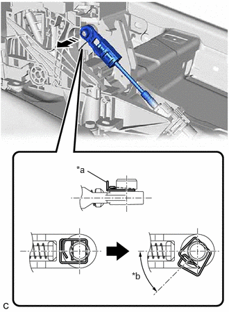
| *a | Clip |
| *b | 45° to 60° |

|
Disconnect in this Direction |
While disengaging the clip as shown in the illustration, disconnect the transmission control cable assembly from the transmission floor shift assembly together with the clip.
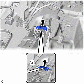
| *a | Stopper |
Using a screwdriver, pull out the stopper of the transmission control cable assembly.
- NOTICE:
-
Do not remove the stopper. If it is removed, reinstall it to its original position.
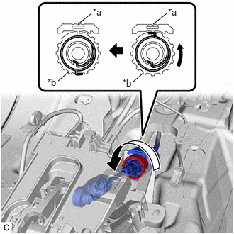
| *a | Stopper |
| *b | Nut |
Rotate the nut counterclockwise approximately 180° and, while holding the nut in that position, disconnect the transmission control cable assembly from the transmission floor shift assembly.
- NOTICE:
- ·
Do not rotate the nut excessively as the interior spring may come off and the transmission control cable assembly will not be reusable.
·Do not forcibly pull the transmission control cable assembly into the cabin.
Push the 2 claws together at the top of the lock piece. While holding the 2 claws together, push the 2 lugs on the bottom of the lock piece toward each other and upward to push up the lock piece.
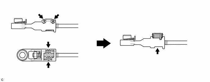
| *a | Lock Piece | *b | Bottom View |
| *c | Push | *d | Push up |
Turn the nut of the transmission control cable assembly 180° counterclockwise. While holding the nut in place, push in the stopper until it clicks twice.
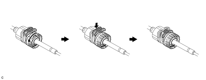
| *a | Stopper | *b | Nut |
| *c | Push in | - | - |
Connect the transmission control cable assembly to the transmission floor shift assembly. Check that the spring is positioned at "A" and push in the stopper.
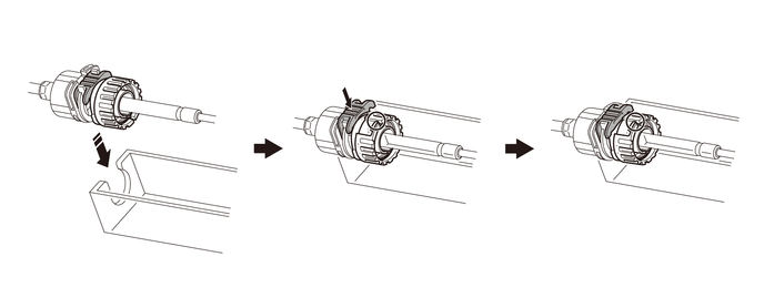
| *1 | Transmission Floor Shift Assembly | - | - |
| *a | Stopper | *b | Spring |
| *c | Nut | *d | Push in |
|
|
Connect in this Direction | - | - |
- NOTICE:
- ·
If the stopper cannot be pushed in, slightly turn the nut clockwise and then push in the stopper again.
·Make sure that the transmission control cable assembly is securely locked.
·Do not forcibly pull the transmission control cable assembly into the cabin.
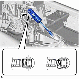
| *a | Correct |
| *b | Incorrect |
|
|
Connect in this Direction |
Connect the transmission control cable assembly to the transmission floor shift assembly as shown in the illustration.
- NOTICE:
-
Connect the transmission control cable assembly so that its adjustment lock section is on the passenger side.
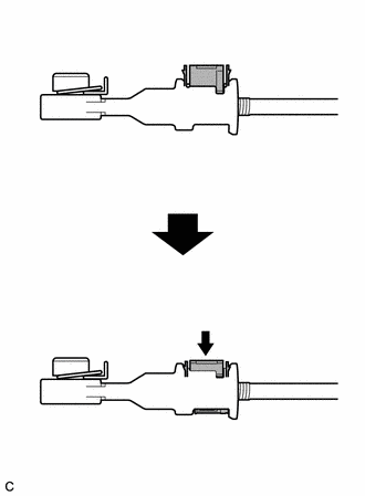
| *a | Lock Piece |
| *b | Adjuster Case |
| *c | Push in |
Push in the lock piece of the adjuster case to lock it.
- NOTICE:
- ·
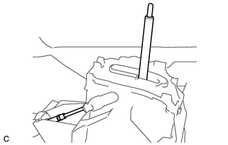 0.667,1.167 0.792,1.167 0.792,1.167 1.042,1.698 true 1.76,0.333 2.177,0.333 false 0.479,1.094 0.719,1.365 0.24,0.271 10 false *1 1.573,0.24 1.896,0.479 0.323,0.24 10 false *a
*1 Transmission Control Cable Assembly *a Lever Shaft
When pushing in the lock piece of the adjuster case to lock it, remove your hand from the lever shaft.
·When pushing in the lock piece of the adjuster case to lock it, do not move the lever shaft or transmission control cable assembly forward or backward.
for PB10 GTMC Made:
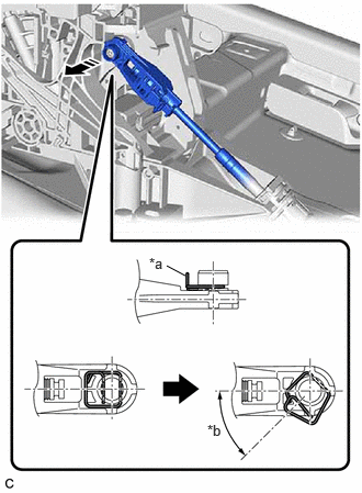
| *a | Clip |
| *b | 45° to 60° |
|
|
Disconnect in this Direction |
While disengaging the clip as shown in the illustration, disconnect the transmission control cable assembly from the transmission floor shift assembly together with the clip.
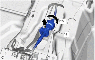
| *a | Lock Nut |
| *b | Clockwise |
|
|
Disconnect in this Direction |
Rotate the lock nut clockwise approximately 180° and, while holding the lock nut in that position, disconnect the transmission control cable assembly from the transmission floor shift assembly.
- NOTICE:
-
Do not forcibly pull the transmission control cable assembly into the cabin.
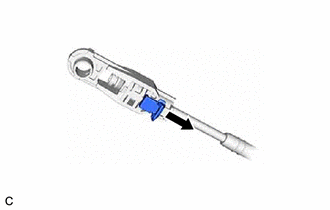
| *a | Slide |
| *b | Adjuster Case Cover |
Slide the adjuster case cover in the direction shown by the arrow.
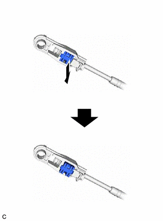
| *a | Pull out |
| *b | Lock Piece |
| *c | Adjuster Case |
Using a precision screwdriver, pull out the lock piece of the adjuster case.
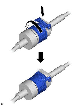
| *a | Lock Nut |
| *b | Push in |
| *c | Stopper |
Turn the lock nut of the transmission control cable assembly counterclockwise. While holding the lock nut, push in the stopper.
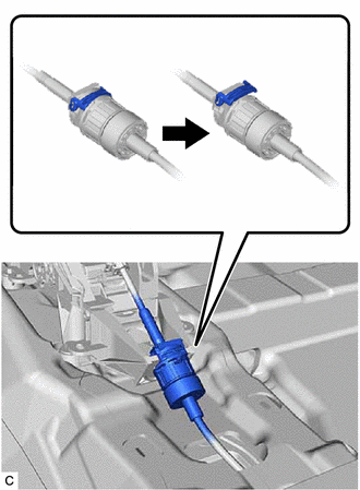
| *a | Stopper |
Connect the transmission control cable assembly to the transmission floor shift assembly.
- NOTICE:
- ·
After installation, check that the outer part of the stopper is as shown in the illustration.
·Do not forcibly pull the transmission control cable assembly into the cabin.
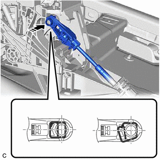
| *a | Correct |
| *b | Incorrect |
|
|
Connect in this Direction |
Connect the transmission control cable assembly to the transmission floor shift assembly as shown in the illustration.
- NOTICE:
-
Connect the transmission control cable assembly so that its adjustment lock section is on the passenger side.
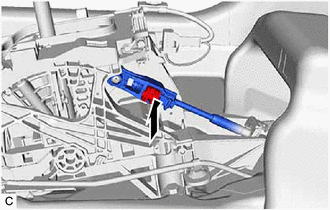
| *a | Push in |
| *b | Lock Piece |
| *c | Adjuster Case |
Push in the lock piece of the adjuster case to lock it.
- NOTICE:
- ·
0.667,1.167 0.792,1.167 0.792,1.167 1.042,1.698 true 1.76,0.333 2.177,0.333 false 0.479,1.094 0.719,1.365 0.24,0.271 10 false *1 1.573,0.24 1.896,0.479 0.323,0.24 10 false *a
*1 Transmission Control Cable Assembly *a Lever Shaft
When pushing in the lock piece of the adjuster case to lock it, remove your hand from the lever shaft.
·When pushing in the lock piece of the adjuster case to lock it, do not move the lever shaft or transmission control cable assembly forward or backward.
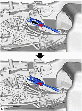
| *a | Adjuster Case Cover |
| *b | Lock Piece |
Move the adjuster case cover in the direction shown by the arrow.
- NOTICE:
-
If the adjuster case cover is not moved far enough so that the adjuster case cover engages the lock piece, the transmission control cable assembly will not be able to lock, and reliable shift operation will not be possible.
58861B
6.INSTALL NO. 1 CONSOLE BOX DUCT
58862B
7.INSTALL NO. 2 CONSOLE BOX DUCT
8.INSTALL CONSOLE BOX ASSEMBLY