LIGHTING (EXT) LIGHTING SYSTEM(except NR Series Engine) Back-up Light Circuit
DESCRIPTION
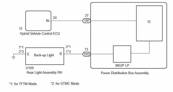
The hybrid vehicle control ECU controls the back-up lights via the BKUP LP relay.
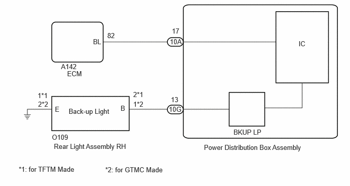
The ECM controls the back-up lights via the BKUP LP relay.
WIRING DIAGRAM
for HV Model
for Gasoline Model
CAUTION / NOTICE / HINT
- NOTICE:
- ·
Inspect the fuses for circuits related to this system before performing the following procedure.
·Before replacing the hybrid vehicle control ECU, refer to Service Bulletin.*1
·Before replacing the ECM, refer to Service Bulletin.*2
*1: for HV Model
*2: for Gasoline Model
PROCEDURE
Choose the model to be inspected.
- Result:
Result Proceed to for HV Model A for Gasoline Model B
A
B
Check if hybrid control system DTCs are output.
- Powertrain > Hybrid Control > Trouble Codes
- 50001 397
- Result:
Result Proceed to DTCs are not output A DTCs are output B
A
B
Disconnect the 10F power distribution box assembly connector.
Disconnect the I3 hybrid vehicle control ECU connector.
Measure the resistance according to the value(s) in the table below.
- Standard Resistance:
Tester Connection Condition Specified Condition I3-24 (BL) - 10F-27 Always Below 1 Ω I3-24 (BL) or 10F-27 - Body ground Always 10 kΩ or higher
- Result:
Proceed to OK NG
OK
NG
Measure the voltage according to the value(s) in the table below.
- Standard Voltage:
Tester Connection Condition Specified Condition 10F-27 - Body ground Ignition switch ON, shift lever not in R Below 1 V 10F-27 - Body ground Ignition switch on (IG), shift lever in R 11 to 14 V
- Result:
Proceed to OK NG
OK
NG
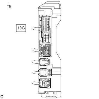
| *a | Component with harness connected
(Power Distribution Box Assembly) |
Measure the voltage according to the value(s) in the table below.
- Standard Voltage:
Tester Connection Condition Specified Condition 10G-13 - Body ground Ignition switch ON, shift lever not in R Below 1 V 10G-13 - Body ground Ignition switch ON, shift lever in R 11 to 14 V
- Result:
Proceed to OK NG
OK
NG
Check if SFI system DTCs are output.
- Powertrain > Engine > Trouble Codes
- 50001 372
- Result:
Result Proceed to DTCs are not output A DTCs are output B
A
B
for M15B-FKS: Click hereEngine / Hybrid System>M15B-FKS (ENGINE CONTROL)>SFI SYSTEM>DIAGNOSTIC TROUBLE CODE CHART202304,999999,_51,_096196,_0456237,RM100000002BAMI,
for M15C-FKS: Click hereEngine / Hybrid System>M15C-FKS (ENGINE CONTROL)>SFI SYSTEM>DIAGNOSTIC TROUBLE CODE CHART202304,999999,_51,_096205,_0456238,RM100000002BG0F,
for M20A-FKS: Click hereEngine / Hybrid System>M20A-FKS (ENGINE CONTROL)>SFI SYSTEM>DIAGNOSTIC TROUBLE CODE CHART202304,999999,_51,_101144,_0469422,RM100000002BDZM,
for M20C-FKS: Click hereEngine / Hybrid System>M20C-FKS (ENGINE CONTROL)>SFI SYSTEM>DIAGNOSTIC TROUBLE CODE CHART202304,999999,_51,_105190,_0484152,RM100000002BG1R,
for M20E-FKS: Click hereEngine / Hybrid System>M20E-FKS (ENGINE CONTROL)>SFI SYSTEM>DIAGNOSTIC TROUBLE CODE CHART202304,999999,_51,_101153,_0478272,RM100000002BG35,
Disconnect the 10A power distribution box assembly connector.
Disconnect the A142 ECM connector.
Measure the resistance according to the value(s) in the table below.
- Standard Resistance:
Tester Connection Condition Specified Condition A142-82 (BL) - 10A-17 Always Below 1 Ω A142-82 (BL) or 10A-17 - Body ground Always 10 kΩ or higher
- Result:
Proceed to OK NG
OK
NG
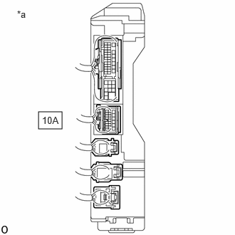
| *a | Component with harness connected
(Power Distribution Box Assembly) |
Measure the voltage according to the value(s) in the table below.
- Standard Voltage:
Tester Connection Condition Specified Condition 10A-17 - Body ground Ignition switch ON, shift lever not in R Below 1 V 10A-17 - Body ground Ignition switch on (IG), shift lever in R 11 to 14 V
- Result:
Proceed to OK NG
OK
NG
for M15B-FKS: Click hereEngine / Hybrid System>M15B-FKS (ENGINE CONTROL)>ECM>REMOVAL202304,999999,_51,_096196,_0456246,RM100000002AYLB,
for M15C-FKS: Click hereEngine / Hybrid System>M15C-FKS (ENGINE CONTROL)>ECM>REMOVAL202304,999999,_51,_096205,_0456262,RM100000002AYLC,
for M20A-FKS: Click hereEngine / Hybrid System>M20A-FKS (ENGINE CONTROL)>ECM>REMOVAL202304,999999,_51,_101144,_0470279,RM100000002AYL8,
for M20C-FKS: Click hereEngine / Hybrid System>M20C-FKS (ENGINE CONTROL)>ECM>REMOVAL202304,999999,_51,_105190,_0481177,RM100000002AYL9,
for M20E-FKS: Click hereEngine / Hybrid System>M20E-FKS (ENGINE CONTROL)>ECM>REMOVAL202304,999999,_51,_101153,_0477097,RM100000002AYLA,
| *a | Component with harness connected
(Power Distribution Box Assembly) |
Measure the voltage according to the value(s) in the table below.
- Standard Voltage:
Tester Connection Condition Specified Condition 10G-13 - Body ground Ignition switch ON, shift lever not in R Below 1 V 10G-13 - Body ground Ignition switch ON, shift lever in R 11 to 14 V
- Result:
Proceed to OK NG
OK
NG