DOOR LOCK WIRELESS DOOR LOCK CONTROL SYSTEM(except NR Series Engine with Smart Entry and Start System) TERMINALS OF ECU
CHECK POWER DISTRIBUTION BOX ASSEMBLY AND MAIN BODY ECU (MULTIPLEX NETWORK BODY ECU)
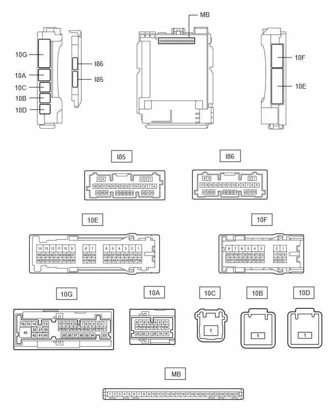
Remove the main body ECU (multiplex network body ECU) from the power distribution box assembly.
Reconnect the power distribution box assembly connector.
Measure the voltage and resistance according to the value(s) in the table below.
- HINT:
-
Measure the values on the wire harness side with the connectors connected.
| Terminal No. (Symbol) | Terminal Description | Condition | Specified Condition |
|---|---|---|---|
| MB-13 (GND1) - Body ground | Ground | Always | Below 1 Ω |
| MB-14 (GND2) - Body ground | Ground | Always | Below 1 Ω |
| MB-26 (BECU) - Body ground | Auxiliary battery power supply | Ignition switch off | 11 to 14 V |
| MB-27 (IGR) - Body ground | IG power supply | Ignition switch ON | 11 to 14 V |
Install the main body ECU (multiplex network body ECU) to the power distribution box assembly.
Measure the voltage and check for pulses according to the value(s) in the table below.
| Terminal No. (Symbol) | Terminal Description | Condition | Specified Condition |
|---|---|---|---|
| 10G-22 (FRCY) - Body ground | Front door courtesy light switch (for RH) input | Front door RH open → closed | Below 1 V → 11 to 14 V or pulse output (maximum 14 V)* |
| 10G-23 (FLCY) - Body ground | Front door courtesy light switch (for LH) input | Front door LH open → closed | Below 1 V → 11 to 14 V or pulse output (maximum 14 V)* |
| 10G-27 (RCTY) - Body ground | Rear door courtesy light switch (for RH) input | Rear door RH open → closed | Below 1 V → 11 to 14 V or pulse output (maximum 14 V)* |
| 10G-18 (LCTY) - Body ground | Rear door courtesy light switch (for LH) input | Rear door LH open → closed | Below 1 V → 11 to 14 V or pulse output (maximum 14 V)* |
| 10G-5 (LGCY) -Body ground | Luggage compartment door courtesy light switch input | Luggage compartment door open → closed | Below 1 V → 11 to 14 V or pulse output (maximum 14 V)* |
| 10G-32 (TR+) - Body ground | Luggage compartment door lock motor drive output | Luggage compartment door closed → open | Below 1 V → 11 to 14 V → Below 1 V |
| 10E-7 (ACTD) - Body ground | Door lock motor unlock drive output | Door control switch or driver door key cylinder off → on (unlock) | Below 1 V → 11 to 14 V → Below 1 V |
| 10G-34 (ACT-) - Body ground | |||
| 10G-35 (ACT-) - Body ground | |||
| 10G-37 (ACT+) - Body ground | Door lock motor lock drive output | Door control switch or driver door key cylinder off → on (lock) | Below 1 V → 11 to 14 V → Below 1 V |
| I85-3 (LSFR) - Body ground | Front door RH unlock detection switch input | Front door RH unlocked → locked | Below 1 V → 11 to 14 V or pulse output (maximum 14 V)* |
| I85-9 (LSFL) - Body ground | Front door LH unlock detection switch input | Front door LH unlocked → locked | Below 1 V → 11 to 14 V or pulse output (maximum 14 V)* |
| I86-23 (LSWR) - Body ground | Rear door RH unlock detection switch input | Rear door RH unlocked → locked | Below 1 V → 11 to 14 V or pulse output (maximum 14 V)* |
| I85-10 (LSWL) - Body ground | Rear door LH unlock detection switch input | Rear door LH unlocked → locked | Below 1 V → 11 to 14 V or pulse output (maximum 14 V)* |
| I85-28 (L2) - Body ground | Driver door key-linked lock input | Driver door key cylinder turned to lock | Below 1 V |
| Driver door key cylinder not turned | Pulse generation | ||
| I85-4 (UL3) - Body ground | Driver door key-linked unlock input | Driver door key cylinder turned to unlock | Below 1 V |
| Driver door key cylinder not turned | Pulse generation |
*: Differs depending on the vehicle model
CHECK CERTIFICATION ECU (SMART KEY ECU ASSEMBLY)
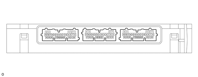
Disconnect the I196 certification ECU (smart key ECU assembly) connector.
Measure the voltage and resistance according to the value(s) in the table below.
| Terminal No. (Symbol) | Terminal Description | Condition | Specified Condition |
|---|---|---|---|
| I196-29 (E) - Body ground | Ground | Always | Below 1 Ω |
| I196-6 (+B) - Body ground | Auxiliary battery power supply | Ignition switch off | 11 to 14 V |
Reconnect the I196 certification ECU (smart key ECU assembly) connector.
Check for pulses according to the value(s) in the table below.
| Tester Connection | Terminal Description | Condition | Specified Condition |
|---|---|---|---|
| O174-21 (RCO) - I196-29 (E) | Output to electrical key and tire pressure warning ECU and receiver
(Power supply for electrical key and tire pressure warning ECU and receiver. Certification ECU (smart key ECU assembly) outputs 5 V when receiver starts operating.) |
Proceed:
1.
Ignition switch off 2.
Bring electrical key transmitter sub-assembly outside detection area but within wireless function operational area 3.
Lock or unlock switch of electrical key transmitter sub-assembly not pressed → pressed |
Pulse generation
(See waveform 1) |
| O174-12 (CSEL) - I196-29 (E) | Communication channel switching circuit | Proceed:
1.
Ignition switch off 2.
Close all doors |
No pulse generation → Pulse generation |
| O174-11 (RDAM) - I196-29 (E) | Electrical key and tire pressure warning ECU and receiver communication circuit | Proceed:
1.
Ignition switch off 2.
All doors locked 3.
Bring electrical key transmitter sub-assembly outside detection area but within wireless function operational area 4.
Lock or unlock switch of electrical key transmitter sub-assembly not pressed → pressed |
Pulse generation
(See waveform 2) |
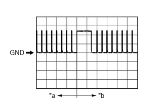
| *a | Before lock or unlock switch of electrical key transmitter sub-assembly pressed |
| *b | After lock or unlock switch of electrical key transmitter sub-assembly pressed |
Using an oscilloscope, check waveform 1.
- NOTICE:
-
The oscilloscope waveform shown in the illustration is an example for reference only. Noise, chattering, etc. are not shown.
| Item | Content |
|---|---|
| Tester Connection | O174-21 (RCO) - I196-29 (E) |
| Tool Setting | 2 V/DIV., 500 ms./DIV. |
| Condition | Procedure:
1.
Ignition switch off 2.
Electrical key transmitter sub-assembly brought outside detection area but kept inside wireless function operational area 3.
Lock or unlock switch of electrical key transmitter sub-assembly not pressed → pressed |
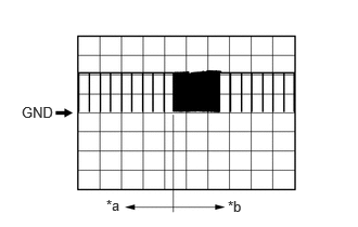
| *a | Before lock or unlock switch of electrical key transmitter sub-assembly pressed |
| *b | After lock or unlock switch of electrical key transmitter sub-assembly pressed |
Using an oscilloscope, check waveform 2.
- NOTICE:
-
The oscilloscope waveform shown in the illustration is an example for reference only. Noise, chattering, etc. are not shown.
| Item | Content |
|---|---|
| Tester Connection | O174-11 (RDAM) - I196-29 (E) |
| Tool Setting | 5 V/DIV., 500 ms./DIV. |
| Condition | Procedure:
1.
Ignition switch off 2.
All doors locked 3.
Electrical key transmitter sub-assembly not inside vehicle 4.
Electrical key transmitter sub-assembly brought outside detection area but kept inside wireless function operational area 5.
Lock or unlock switch of electrical key transmitter sub-assembly not pressed → pressed |