8ZR-FXE ENGINE MECHANICAL CAMSHAFT REMOVAL
CAUTION / NOTICE / HINT
The necessary procedures (adjustment, calibration, initialization, or registration) that must be performed after parts are removed and installed, or replaced during camshaft removal/installation are shown below.
| Replaced Part or Performed Procedure | Necessary Procedure | Effect/Inoperative Function when Necessary Procedure not Performed | Link |
|---|---|---|---|
·
Replacement of throttle body assembly ·
Replacement of camshaft (for intake or exhaust camshaft) ·
Replacement of camshaft timing gear assembly ·
Replacement of ignition coil assembly |
Inspection after repair | ·
Poor idle, etc. ·
Engine start function, etc. |
( 202304,999999,_51,_080778,_0393982,RM100000002BDLI,) 202304,999999,_51,_080778,_0393982,RM100000002BDLI,)
|
- HINT:
-
When the cable is disconnected / reconnected to the auxiliary battery terminal, systems temporarily stop operating. However, each system has a function that completes learning the first time the system is used.
Learning completes when vehicle is driven Effect/Inoperative Function when Necessary Procedure not Performed Necessary Procedure Link Front Camera System Drive the vehicle straight ahead at 15 km/h (9 mph) or more for 1 second or more. ( 202304,999999,_95,_139716,_0584193,RM1000000029F4C,)
PROCEDURE

 51410
1.REMOVE NO. 1 ENGINE UNDER COVER ASSEMBLY
51410
1.REMOVE NO. 1 ENGINE UNDER COVER ASSEMBLY
2.DRAIN ENGINE COOLANT (for Engine)
3.REMOVE WINDSHIELD WIPER MOTOR AND LINK
55737B
4.REMOVE NO. 1 HEATER AIR DUCT SPLASH SHIELD SEAL (w/ No. 1 Heater Air Duct Splash Shield Seal)
55701J
5.REMOVE OUTER COWL TOP PANEL SUB-ASSEMBLY
33820B
6.DISCONNECT TRANSMISSION CONTROL CABLE ASSEMBLY
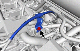
Remove the bolt to disconnect the transmission control cable assembly from the cylinder head cover sub-assembly.
12262
7.DISCONNECT NO. 2 VENTILATION HOSE
19500
8.REMOVE IGNITION COIL ASSEMBLY
11101E
9.REMOVE CAMSHAFT POSITION SENSOR
82121
10.DISCONNECT ENGINE WIRE
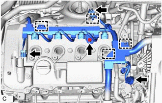
Disconnect the 3 connectors.
Disengage the 4 clamps.
Remove the bolt and disconnect the engine wire from the cylinder head cover sub-assembly.
23829A
11.DISCONNECT FUEL VAPOR FEED HOSE
25610
12.REMOVE EGR PIPE ASSEMBLY
16296
13.DISCONNECT NO. 8 WATER BY-PASS HOSE
16297
14.DISCONNECT NO. 9 WATER BY-PASS HOSE
17650G
15.REMOVE PURGE VALVE (PURGE VSV)
23818
16.REMOVE FUEL VAPOR FEED PIPE
11201
17.REMOVE CYLINDER HEAD COVER SUB-ASSEMBLY
11213
18.REMOVE CYLINDER HEAD COVER GASKET
11193
19.REMOVE SPARK PLUG TUBE GASKET
20.SET NO. 1 CYLINDER TO TDC (COMPRESSION)
Set the No. 1 cylinder to TDC (Compression).
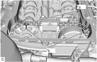
| *a | Paint Mark |
| *b | Timing Mark |
Place paint marks on the chain sub-assembly in alignment with the timing marks on the camshaft timing gear assembly and camshaft timing sprocket.
13562
21.REMOVE NO. 2 CHAIN VIBRATION DAMPER
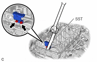
Using SST, remove the 2 bolts and No. 2 chain vibration damper from the No. 1 camshaft bearing cap.
- SST
- 09961-00950
13540
22.REMOVE NO. 1 CHAIN TENSIONER ASSEMBLY
13523G
23.REMOVE CAMSHAFT TIMING SPROCKET
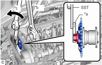
| *a | 14 mm Union Nut Wrench |
| *b | Hold |
| *c | Turn |
While holding the hexagonal portion of the No. 2 camshaft with a wrench, remove the bolt with SST and 14 mm union nut wrench.
- SST
- 09961-00950
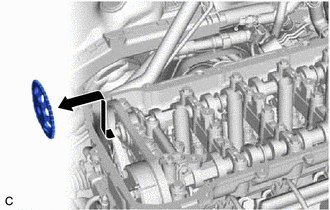
While removing the chain sub-assembly, pull out the camshaft timing sprocket horizontally and then upward.
13050
24.INSPECT CAMSHAFT TIMING GEAR ASSEMBLY
25.REMOVE CAMSHAFT BEARING CAP
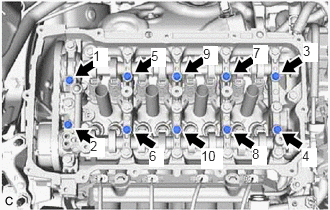
Uniformly loosen and remove the 10 bolts in the order shown in the illustration.
- NOTICE:
-
Do not loosen the other 10 bearing cap bolts in this step.
- HINT:
-
Arrange the removed parts in such a way that they can be reinstalled to their original locations.
Remove the bolts and camshaft bearing caps in the order shown in the illustration. Immediately after removing each camshaft bearing cap, install service bolts and spacers in the order shown in the illustration.
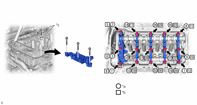
| *a | The removal order of the parts | *b | The installation order of the service bolts and spacers for temporarily tightening the camshaft housing sub-assembly |
| *c | Service bolt and spacer (Used to temporarily secure the camshaft housing sub-assembly) | - | - |
- Torque:
- 27 N*m (275 kgf*cm, 20 ft.*lbf)
- NOTICE:
- ·
If the bolts are loosened all at once, seal packing on the camshaft housing sub-assembly and cylinder head sub-assembly may separate, resulting in oil leaks. Therefore, be sure to install the service bolts and spacers to one camshaft bearing cap at a time.
·Do not install the camshaft bearing caps when installing the service bolts and spacers.
- HINT:
- ·
Arrange the removed parts in such a way that they can be reinstalled to their original locations.
·Part number for the service bolt used to temporarily secure the camshaft housing sub-assembly: 91551-G0875 (15 bolts)
·Part number for the spacer used to temporarily secure the camshaft housing sub-assembly: 90387-12048 (15 spacers)
13512
26.REMOVE NO. 2 CAMSHAFT
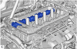
Remove the No. 2 camshaft from the camshaft housing sub-assembly.
13511
27.REMOVE CAMSHAFT
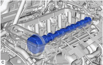
Hold up the chain sub-assembly and remove the camshaft from the camshaft housing sub-assembly.
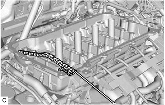
Suspend the chain sub-assembly with a string or equivalent.
13050
28.REMOVE CAMSHAFT TIMING GEAR ASSEMBLY
Secure the hexagonal portion of the camshaft in a soft jaw vise.
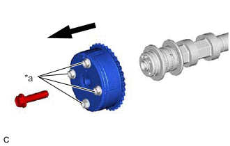
| *a | Do not remove |
Remove the bolt and camshaft timing gear assembly.
- NOTICE:
- ·
Before removing the camshaft timing gear assembly, make sure that the lock pin has been released.
·Do not remove the other 4 bolts.
·Keep the camshaft timing gear assembly horizontal while removing it from the camshaft.
·If the camshaft timing gear assembly is to be reused, be sure to install it with the lock pin released.
29.REMOVE NO. 1 CAMSHAFT BEARING
30.REMOVE NO. 2 CAMSHAFT BEARING