NETWORKING LIN COMMUNICATION SYSTEM(except NR Series Engine) B232588 Door LIN Bus off
DESCRIPTION
If the main body ECU (multiplex network body ECU) detects a communication error with an ECU connected to the door bus lines for 8 seconds or more, DTC B232588 will be stored.
| DTC No. | Detection Item | DTC Detection Condition | Trouble Area | DTC Output from |
|---|---|---|---|---|
| B232588 | Door LIN Bus off | The main body ECU (multiplex network body ECU) detects a communication error with an ECU connected to the door bus lines for 8 seconds or more. | ·
Main body ECU (multiplex network body ECU) ·
Power distribution box assembly ·
Multiplex network master switch assembly ·
Power window regulator motor assembly (driver door) ·
Power window regulator motor assembly (front passenger door) ·
Power window regulator motor assembly (rear LH door) ·
Power window regulator motor assembly (rear RH door) ·
Sliding roof ECU (sliding roof drive gear sub-assembly)* ·
Wire harness or connector |
Main Body |
*: w/ Sliding Roof System
WIRING DIAGRAM
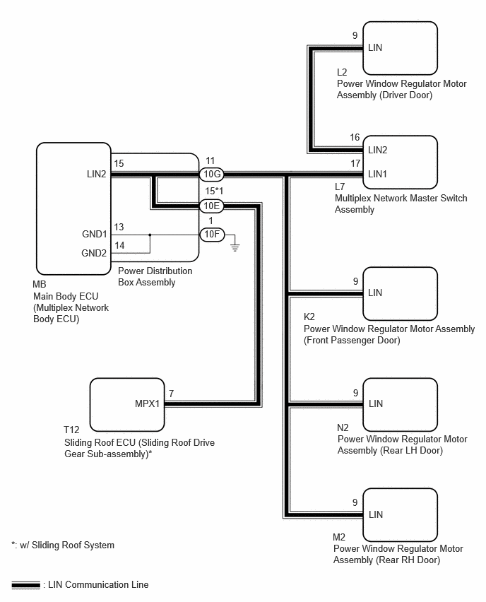
CAUTION / NOTICE / HINT
- NOTICE:
- ·
When a power window regulator motor assembly is replaced or removed and reinstalled, it is necessary to perform initialization.
·When the sliding roof ECU (sliding roof drive gear sub-assembly) is replaced or removed and reinstalled, it is necessary to perform initialization.*
*: w/ Sliding Roof System
·Before replacing the main body ECU (multiplex network body ECU), refer to Registration.*
*: w/ Smart Entry and Start System
PROCEDURE
Disconnect the L2 power window regulator motor assembly (driver door) connector.
Clear the DTCs.
- Body Electrical > Main Body > Clear DTCs
- 50002 449
After 10 seconds have elapsed, check if the same DTC is output again.
- Body Electrical > Main Body > Trouble Codes
- 50001 449
- Result:
Result Proceed to DTC B232588 is output A DTC B232588 is not output B
A
B
Disconnect the L7 multiplex network master switch assembly connector.
Clear the DTCs.
- Body Electrical > Main Body > Clear DTCs
- 50002 449
After 10 seconds have elapsed, check if the same DTC is output again.
- Body Electrical > Main Body > Trouble Codes
- 50001 449
- Result:
Result Proceed to DTC B232588 is output A DTC B232588 is not output B
A
B
Disconnect the K2 power window regulator motor assembly (for front passenger door) connector.
Clear the DTCs.
- Body Electrical > Main Body > Clear DTCs
- 50002 449
After 10 seconds have elapsed, check if the same DTC is output again.
- Body Electrical > Main Body > Trouble Codes
- 50001 449
- Result:
Result Proceed to DTC B232588 is output A DTC B232588 is not output B
A
B
Disconnect the M2 power window regulator motor assembly (rear RH door) connector.
Clear the DTCs.
- Body Electrical > Main Body > Clear DTCs
- 50002 449
After 10 seconds have elapsed, check if the same DTC is output again.
- Body Electrical > Main Body > Trouble Codes
- 50001 449
- Result:
Result Proceed to DTC B232588 is output A DTC B232588 is not output B
A
B
Disconnect the N2 power window regulator motor assembly (rear LH door) connector.
Clear the DTCs.
- Body Electrical > Main Body > Clear DTCs
- 50002 449
After 10 seconds have elapsed, check if the same DTC is output again.
- Body Electrical > Main Body > Trouble Codes
- 50001 449
- Result:
Result Proceed to DTC B232588 is output A DTC B232588 is not output B
A
B
Check the vehicle specification.
- Result:
Result Proceed to w/ Sliding Roof System A w/o Sliding Roof System B
A
B
Disconnect the T12 sliding roof ECU (sliding roof drive gear sub-assembly) connector.
Clear the DTCs.
- Body Electrical > Main Body > Clear DTCs
- 50002 449
After 10 seconds have elapsed, check if the DTC is output.
- Body Electrical > Main Body > Trouble Codes
- 50001 449
- Result:
Result Proceed to DTC B232588 is output A DTC B232588 is not output B
A
B
Disconnect the 10G and 10E* power distribution box assembly assembly connector.
*: w/ Sliding Roof System
Disconnect all connectors shown in the wiring diagram.
Measure the resistance according to the value(s) in the table below.
- Standard Resistance:
Tester Connection Condition Specified Condition 10G-11 - Body ground Always 10 kΩ or higher 10G-11 - Other terminals Always 10 kΩ or higher 10E-15 - Body ground* Always 10 kΩ or higher 10E-15 - Other terminals* Always 10 kΩ or higher
*: w/ Sliding Roof System
- Result:
Proceed to OK NG
OK
NG
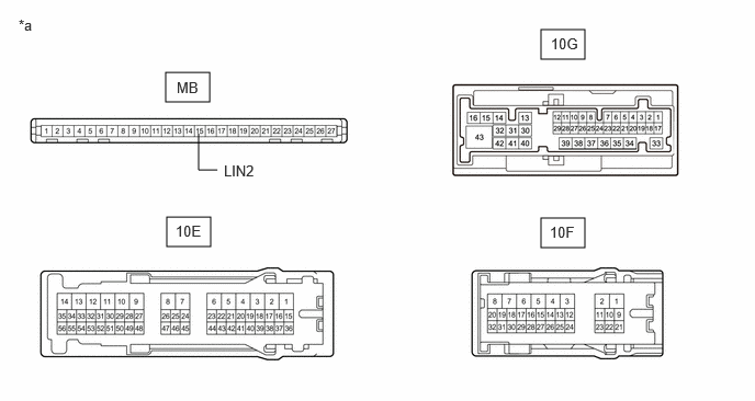
| *a | Component without harness connected
(Power Distribution Box Assembly) |
- | - |
Remove the power distribution box assembly.
Remove the main body ECU (multiplex network body ECU) from the power distribution box assembly.
Measure the resistance according to the value(s) in the table below.
- HINT:
-
This inspection is to check the LIN communication line in the power distribution box assembly that connects the wire harness to the built-in main body ECU (multiplex network body ECU).
- Standard Resistance:
Tester Connection Condition Specified Condition 10G-11 - 10F-1*1 Always 10 kΩ or higher 10G-11 or 10E-15 - 10F-1*2 Always 10 kΩ or higher MB-15 (LIN2) - Other terminals Always 10 kΩ or higher
*1: w/o Sliding Roof System
*2: w/ Sliding Roof System
- Result:
Proceed to OK NG
OK
NG
Install the main body ECU (multiplex network body ECU) to the power distribution box assembly.
Connect all power distribution box assembly connectors other than 10G and 10E.

| *a | Component with harness connected
(Power Distribution Box Assembly) |
*b | Waveform |
Using a GTS, check the waveform.
- HINT:
-
This inspection is to check the LIN communication line in the power distribution box assembly that connects the wire harness to the built-in main body ECU (multiplex network body ECU).
- OK:
Tester Connection Condition Tool Setting Specified Condition 10G-11 - Body ground Ignition switch ON 2 V/DIV., 200 ms/DIV. Pulse generation
(See waveform)10E-15 - Body ground* Ignition switch ON 2 V/DIV., 200 ms/DIV. Pulse generation
(See waveform)
*: w/ Sliding Roof System
- Result:
Proceed to OK NG
OK
NG
Measure the resistance according to the value(s) in the table below.
- Standard Resistance:
Tester Connection Condition Specified Condition L7-16 (LIN2) - Body ground Always 10 kΩ or higher L7-16 (LIN2) - Other terminals Always 10 kΩ or higher
- Result:
Proceed to OK NG
OK
NG