THEFT DETERRENT / KEYLESS ENTRY SMART ENTRY AND START SYSTEM(for Entry Function (except NR Series)) Driver Side Door Entry Lock Function does not Operate
DESCRIPTION
If the entry lock function does not operate for the driver door only, but the entry unlock function operates, the request code is being transmitted properly from the driver door. In this case, there may be a problem related to the lock sensor (connection between the certification ECU (smart key ECU assembly) and front door outside handle assembly (for driver door)).
WIRING DIAGRAM
w/o Digital Key System
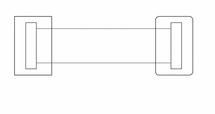
w/ Digital Key System
CAUTION / NOTICE / HINT
- NOTICE:
- ·
When using the GTS with the ignition switch off, connect the GTS to the DLC3 and turn a courtesy light switch on and off at intervals of 1.5 seconds or less until communication between the GTS and the vehicle begins.
Then select Model Code "KEY REGIST" under manual mode and enter the following menus: Body Electrical / Entry&Start(CAN). While using the GTS, periodically turn a courtesy light switch on and off at intervals of 1.5 seconds or less to maintain communication between the GTS and the vehicle.
·The smart entry and start system (for Entry Function) uses the CAN communication system. Inspect the communication function by following How to Proceed with Troubleshooting. Troubleshoot the smart entry and start system (for Entry Function) after confirming that the communication systems are functioning properly.
·Before replacing the certification ECU (smart key ECU assembly) or front door outside handle assembly (for driver door), refer to Service Bulletin.
·Check that there are no electrical key transmitter sub-assemblies in the vehicle.
·After repair, confirm that no DTCs are output.
PROCEDURE
When the door control switch on the multiplex network master switch assembly is operated, check that the doors unlock and lock according to the switch operation.
- OK:
Door locks operate normally.
- Result:
Proceed to OK NG
OK
NG
Check the entry lock function.
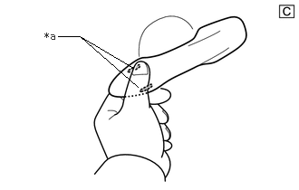
| *a | Lock Sensor |
The illustrations shown are examples only.
Turn the ignition switch off.
Open and close the driver door.
Hold the electrical key transmitter sub-assembly at the same height as the door outside handle assembly and approximately 0.3 m (0.984 ft.) from the driver door.
Touch the lock sensor of the front door outside handle assembly (groove on the front door outside handle) with 2 or more fingers for 2 seconds or more.
- HINT:
- ·
If the door does not lock even when touching the lock sensor for 2 seconds or more, touch it with your palm.
·When checking the operation of the lock sensor again, make sure to perform the procedure from step (1).
·When checking the operation of the entry lock function several times, it can be operated up to 2 times consecutively. To operate the function 3 times or more consecutively, the doors need to be unlocked once. However, this is only for the entry lock function, other door lock operations, such as a wireless door lock operation can be performed consecutively.
- Result:
Result Proceed to Entry function does not operate normally A Entry function operates normally B
A
B
for HV Model: Click hereVehicle Interior>THEFT DETERRENT / KEYLESS ENTRY>SMART ENTRY AND START SYSTEM (for Start Function, HV Model)>CHECK FOR INTERMITTENT PROBLEMS202304,999999,_58,_080747,_0392032,RM100000002BD9N,
for Gasoline Model: Click hereVehicle Interior>THEFT DETERRENT / KEYLESS ENTRY>SMART ENTRY AND START SYSTEM (for Start Function, Gasoline Model (except NR Series))>CHECK FOR INTERMITTENT PROBLEMS202304,999999,_58,_080747,_0600574,RM100000002BD89,
| *a | Lock Sensor |
The illustrations shown are examples only.
Open and close the driver door.
Hold the electrical key transmitter sub-assembly at the same height as the door outside handle assembly and approximately 0.3 m (0.984 ft.) from the driver door.
Read the Data List according to the display on the GTS.
Touch the lock sensor of the front door outside handle assembly (groove on the front door outside handle) with 2 or more fingers for 2 seconds or more.
- HINT:
- ·
If the door does not lock even when touching the lock sensor for 2 seconds or more, touch it with your palm.
·When checking the operation of the lock sensor again, make sure to perform the procedure from step (a).
·When checking the operation of the entry lock function several times, it can be operated up to 2 times consecutively. To operate the function 3 times or more consecutively, the doors need to be unlocked once. However, this is only for the entry lock function, other door lock operations, such as a wireless door lock operation can be performed consecutively.
- Body Electrical > Entry&Start > Data List
-
Tester Display Measurement Item Range Normal Condition Diagnostic Note Driver Side Lock Sensor Driver door touch sensor (lock sensor) OFF or ON OFF: Driver door touch sensor (lock sensor) not touched
ON: Driver door touch sensor (lock sensor) touched·Displays whether the lock sensor is on or off (even if the sensor is touched and contact is maintained, "ON" is displayed only momentarily).
·Use this Data List item to help determine if there is a lock sensor malfunction when the entry lock function does not operate.
- Body Electrical > Entry&Start > Data List
-
Tester Display Driver Side Lock Sensor - 50003 440 5
- OK:
The GTS display changes correctly in response to the operation of the front door outside handle assembly (for driver door).
- Result:
Proceed to OK NG
OK
NG
Disconnect the I196 certification ECU (smart key ECU assembly) connector.
Disconnect the L16*1 or L17*2 front door outside handle assembly (for driver door) connector.
*1: w/o Digital Key System
*2: w/ Digital Key System
Measure the resistance according to the value(s) in the table below.
- Standard Resistance:
w/o Digital Key System: Tester Connection Condition Specified Condition I196-10 (CLG1) - L16-4 (ANT1) Always Below 1 Ω I196-9 (CG1B) - L16-6 (ANT2) Always Below 1 Ω I196-10 (CLG1) or L16-4 (ANT1) - Other terminals and body ground Always 10 kΩ or higher I196-9 (CG1B) or L16-6 (ANT2) - Other terminals and body ground Always 10 kΩ or higher
w/ Digital Key System: Tester Connection Condition Specified Condition I196-10 (CLG1) - L17-4 (ANT1) Always Below 1 Ω I196-9 (CG1B) - L17-6 (ANT2) Always Below 1 Ω I196-10 (CLG1) or L17-4 (ANT1) - Other terminals and body ground Always 10 kΩ or higher I196-9 (CG1B) or L17-6 (ANT2) - Other terminals and body ground Always 10 kΩ or higher
Reconnect the L16*1 or L17*2 front door outside handle assembly (for driver door) connector.
*1: w/o Digital Key System
*2: w/ Digital Key System
Reconnect the I196 certification ECU (smart key ECU assembly) connector.
- Result:
Proceed to OK NG
OK
NG
| *a | Lock Sensor |
The illustrations shown are examples only.
Open and close the driver door.
Hold the electrical key transmitter sub-assembly at the same height as the door outside handle assembly and approximately 0.3 m (0.984 ft.) from the driver door.
Read the Data List according to the display on the GTS.
Touch the lock sensor of the front door outside handle assembly (groove on the front door outside handle) with 2 or more fingers for 2 seconds or more.
- HINT:
- ·
If the door does not lock even when touching the lock sensor for 2 seconds or more, touch it with your palm.
·When checking the operation of the lock sensor again, make sure to perform the procedure from step (a).
·When checking the operation of the entry lock function several times, it can be operated up to 2 times consecutively. To operate the function 3 times or more consecutively, the doors need to be unlocked once. However, this is only for the entry lock function, other door lock operations, such as a wireless door lock operation can be performed consecutively.
- Body Electrical > Entry&Start > Data List
-
Tester Display Measurement Item Range Normal Condition Diagnostic Note Driver Side Lock Sensor Driver door touch sensor (lock sensor) OFF or ON OFF: Driver door touch sensor (lock sensor) not touched
ON: Driver door touch sensor (lock sensor) touched·Displays whether the lock sensor is on or off (even if the sensor is touched and contact is maintained, "ON" is displayed only momentarily).
·Use this Data List item to help determine if there is a lock sensor malfunction when the entry lock function does not operate.
- Body Electrical > Entry&Start > Data List
-
Tester Display Driver Side Lock Sensor - 50003 440 5
- OK:
The GTS display changes correctly in response to the operation of the front door outside handle assembly (for driver door).
- Result:
Proceed to OK NG
OK
NG