THEFT DETERRENT / KEYLESS ENTRY SMART ENTRY AND START SYSTEM(for Entry Function (except NR Series)) OPERATION CHECK
CHECK CUSTOMIZE PARAMETERS
- NOTICE:
-
The operation check below is based on the non-customized initial condition of the vehicle.
CHECK THE ENTRY UNLOCK FUNCTION
Check the entry unlock function.
Perform a wireless lock door operation to lock the door, touch the unlock sensor built into the backside of the front door outside handle assembly of the driver door while carrying the electrical key transmitter sub-assembly and check that the door unlocks.
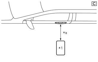
| *1 | Electrical Key Transmitter Sub-assembly |
| *a | 0.7 to 1 m (2.30 to 3.28 ft.) |
The illustrations shown are examples only.
Inspect the entry unlock detection area. Hold the electrical key transmitter sub-assembly at the same height as the door outside handle assembly and approximately 0.7 to 1 m (2.30 to 3.28 ft.) from the vehicle as shown in the illustration and check that the LED (red) of the electrical key transmitter sub-assembly blinks.
With the system in unlock standby mode, grasp the front door outside handle assembly (for driver door) and check that the door unlocks.
- HINT:
- ·
The system is in unlock standby mode when the electrical key transmitter sub-assembly is in the detection area and the key ID code sent by the electrical key transmitter sub-assembly matches the key ID code stored by the certification ECU (smart key ECU assembly).
·Communication may not be possible if the electrical key transmitter sub-assembly is within 0.2 m (0.656 ft.) of the door outside handle assembly.
·Inspect the front passenger door using the same procedure.
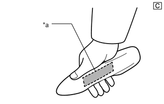
| *a | Unlock Sensor (Backside) |
The illustrations shown are examples only.
Check the unlock response sensitivity. With the system in unlock standby mode, touch the area shown in the illustration and check that the door unlocks.
- NOTICE:
-
If the sensor is touched too quickly or released too slowly, the sensor may not react and the door will not unlock.
- HINT:
-
Inspect the front passenger door using the same procedure.
CHECK THE ENTRY LOCK FUNCTION
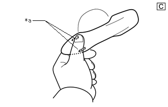
| *a | Lock Sensor |
The illustrations shown are examples only.
Check the entry lock function.
- NOTICE:
-
If the electrical key transmitter sub-assembly is in the vehicle but outside the detection area (on the instrument panel, in the glove box, on the floor) and a door lock operation is performed, the key lock-in prevention function will not operate and the electrical key transmitter sub-assembly will be locked inside the vehicle.
With the door closed and unlocked, touch the lock sensor of the front door outside handle assembly of the driver door while carrying the electrical key transmitter sub-assembly and check that the door locks.
- HINT:
- ·
If the door does not lock even when touching the lock sensor, touch it with your palm.
·Inspect the front passenger door using the same procedure.
| *1 | Electrical Key Transmitter Sub-assembly |
| *a | Approximately 0.3 m (0.984 ft.) |
The illustrations shown are examples only.
Inspect the entry lock operating range. Hold the electrical key transmitter sub-assembly approximately 0.1 m (0.328 ft.) below the bottom edge of the door glass and approximately 0.3 m (0.984 ft.) from the vehicle as shown in the illustration, touch the lock sensor and check that the door locks.
- HINT:
- ·
If the door does not lock even when touching the lock sensor, touch it with your palm.
·As communication may not be possible if the electrical key transmitter sub-assembly is within 0.2 m (0.656 ft.) of the front door outside handle assembly, the door may not lock if the lock sensor is touched with the same hand that is carrying the electrical key transmitter sub-assembly, etc.
·If the key lock-in prevention function buzzer sounds, radio waves from the indoor electrical key antenna may be leaking from the vehicle.
·Inspect the front passenger door using the same procedure.
·The entry lock function cannot be operated more than 3 times consecutively.
CHECK ENTRY LUGGAGE COMPARTMENT DOOR OPEN FUNCTION
Check the entry luggage compartment door open function.
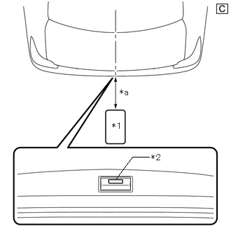
| *1 | Electrical Key Transmitter Sub-assembly |
| *2 | Luggage Electrical Key Switch |
| *a | 0.7 to 1 m (2.30 to 3.28 ft.) |
The illustrations shown are examples only.
Perform a wireless lock operation to lock the doors, operate of the luggage electrical key switch while carrying the electrical key transmitter sub-assembly and check that the luggage compartment door opens.
Inspect the entry luggage compartment open operating range. While standing at the rear of the vehicle, hold the electrical key transmitter sub-assembly so that it is facing the direction shown in the above illustration at the same height as the luggage electrical key switch and approximately 0.7 to 1 m (2.30 to 3.28 ft.) from the vehicle, press the luggage electrical key switch and check that the luggage compartment door opens.
CHECK PUSH-BUTTON START FUNCTION
for HV Model: Click hereVehicle Interior>THEFT DETERRENT / KEYLESS ENTRY>SMART ENTRY AND START SYSTEM (for Start Function, HV Model)>OPERATION CHECK202304,999999,_58,_080747,_0392032,RM100000002BD9O,
for Gasoline Model: Click hereVehicle Interior>THEFT DETERRENT / KEYLESS ENTRY>SMART ENTRY AND START SYSTEM (for Start Function, Gasoline Model (except NR Series))>OPERATION CHECK202304,999999,_58,_080747,_0600574,RM100000002BD8A,
CHECK KEY LOCK-IN PREVENTION FUNCTION (VEHICLE INTERIOR)
- NOTICE:
-
In order to prevent the electrical key transmitter sub-assembly from being locked inside the vehicle, perform this inspection with the window of a door open.
Check the key lock-in prevention function (vehicle interior).
Turn the ignition switch off.
Place the electrical key transmitter sub-assembly on a front or rear seat.
Close all of the doors and make sure they are unlocked.
Touch a door lock sensor and check that the doors do not lock and the key lock-in prevention function buzzer (external) sounds for approximately 5 seconds.
CHECK KEY LOCK-IN PREVENTION FUNCTION (IN LUGGAGE COMPARTMENT)
- NOTICE:
-
In order to prevent the electrical key transmitter sub-assembly from being locked inside the vehicle, perform this inspection with the window of a door open.
-
If the electrical key transmitter sub-assembly is in a metal bag or near a metal object, the key lock-in prevention function may not operate:
Check the key lock-in prevention function (in luggage compartment).
Place the electrical key transmitter sub-assembly in the luggage compartment with all doors locked. Check that: 1) closing the luggage compartment door triggers the combination meter assembly buzzer (which lasts approximately 2 seconds), and 2) pressing the luggage electrical key switch opens the luggage compartment door.
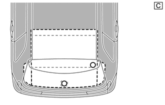
| *a | Inspection Point |
The illustrations shown are examples only.
Inspect the key lock-in prevention detection area. Pay attention to the direction of the electrical key transmitter sub-assembly shown in the illustration. When the electrical key transmitter sub-assembly is in either of the 2 locations in the illustration, check that: 1) closing the luggage compartment door sounds the combination meter assembly buzzer, and 2) pressing the luggage electrical key switch opens the luggage compartment door.
- HINT:
-
Perform the inspection for both inspection points.
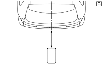
| *1 | Electrical Key Transmitter Sub-assembly |
| *a | 0.1 m or more (0.328 ft. or more) |
The illustrations shown are examples only.
Inspect the key lock-in prevention detection area and the electrical key and tire pressure monitoring system receiver assembly for wave leaks. Hold the electrical key transmitter sub-assembly at the same height as the lower edge of the luggage compartment door aligning it with the center of the rear of the vehicle. Pay attention to the direction and position of the electrical key transmitter sub-assembly shown in the illustration.
- HINT:
- ·
If the combination meter assembly buzzer sounds, the No. 3 indoor electrical key antenna assembly (inside luggage compartment) may have a wave leak.
·When the electrical key transmitter sub-assembly is over 0.1 m (0.328 ft.) from the rear bumper, the combination meter assembly buzzer does not sound.
CHECK ANSWER-BACK FUNCTION
Check the answer-back function (hazard warning light flashing).
| Entry Operation | Hazard Warning Light |
|---|---|
| Entry Lock | Flashes once |
| Entry Unlock | Flashes twice |
CHECK TRANSMITTER BATTERY SAVING MODE FUNCTION
for HV Model: Click hereVehicle Interior>THEFT DETERRENT / KEYLESS ENTRY>SMART ENTRY AND START SYSTEM (for Start Function, HV Model)>OPERATION CHECK202304,999999,_58,_080747,_0392032,RM100000002BD9O,
for Gasoline Model: Click hereVehicle Interior>THEFT DETERRENT / KEYLESS ENTRY>SMART ENTRY AND START SYSTEM (for Start Function, Gasoline Model (except NR Series))>OPERATION CHECK202304,999999,_58,_080747,_0600574,RM100000002BD8A,
CHECK ENTRY CANCEL FUNCTION
for HV Model: Click hereVehicle Interior>THEFT DETERRENT / KEYLESS ENTRY>SMART ENTRY AND START SYSTEM (for Start Function, HV Model)>OPERATION CHECK202304,999999,_58,_080747,_0392032,RM100000002BD9O,
for Gasoline Model: Click hereVehicle Interior>THEFT DETERRENT / KEYLESS ENTRY>SMART ENTRY AND START SYSTEM (for Start Function, Gasoline Model (except NR Series))>OPERATION CHECK202304,999999,_58,_080747,_0600574,RM100000002BD8A,
KEY DIAGNOSTIC MODE (Using GTS)
- HINT:
- ·
With key diagnostic mode, it is possible to check if the electrical key transmitter sub-assembly is operating properly with the selected electrical key antenna and within the selected detection area by the sounding of the combination meter assembly buzzer.
·If the combination meter assembly buzzer sounds with [CH1] displayed but not with [CH2], the electrical key transmitter sub-assembly cannot be detected by channel 2 due to a malfunction, such as wave interference.
Enter the following menus: Body Electrical / Entry&Start / Utility / Communication Check(Key Diag Mode).
- Body Electrical > Entry&Start > Utility
-
Tester Display Communication Check(Key Diag Mode) - 50005 440 2541
Inspect the appropriate item according to the following table.
| Tester Display | Inspection Item |
|---|---|
| [CH1/CH2] Overhead + Driver Side*1 | Front door outside handle assembly (electrical key antenna) (for driver door) |
| [CH1] Overhead + Driver Side*1 | |
| [CH2] Overhead + Driver Side*1 | |
| [CH1/CH2] Overhead + Passenger Side*2 | Front door outside handle assembly (electrical key antenna) (for front passenger door) |
| [CH1] Overhead + Passenger Side*2 | |
| [CH2] Overhead + Passenger Side*2 | |
| [CH1/CH2] Overhead + Front Room*3 | No. 1 indoor electrical key antenna assembly (front floor) |
| [CH1] Overhead + Front Room*3 | |
| [CH2] Overhead + Front Room*3 | |
| [CH1/CH2] Luggage (inside)+ Luggage (inside)*4 | No. 3 indoor electrical key antenna assembly (inside luggage compartment) |
| [CH1] Luggage (inside)+ Luggage (inside)*4 | |
| [CH2] Luggage (inside)+ Luggage (inside)*4 | |
| [CH1/CH2] Luggage+ Luggage (inside)*5 | Electrical key antenna (outside luggage compartment) |
| [CH1] Luggage+ Luggage (inside)*5 | |
| [CH2] Luggage+ Luggage (inside)*5 | |
| [CH1/CH2] Immobiliser Amp*6 | Amplifier (power switch*7, engine switch*8) |
| [CH1] Immobiliser Amp*6 | |
| [CH2] Immobiliser Amp*6 |
*7: for HV Model
*8: for Gasoline Model
[CH1]: Channel 1 is set.
[CH2]: Channel 2 is set.
[CH1/CH2]: Channel 1 and 2 switch automatically at a specific interval*9.
*9: If the electrical key transmitter sub-assembly is detected with either channel 1 or 2, the combination meter assembly buzzer sounds.
Bring the electrical key transmitter sub-assembly near the selected electrical key antenna and check that the combination meter assembly buzzer sounds.
| *1 | Electrical Key Transmitter Sub-assembly |
| *a | 0.7 to 1 m (2.30 to 3.28 ft.) |
The illustrations shown are examples only.
*1: Front door outside handle assembly (for driver door)
- HINT:
- ·
Hold the electrical key transmitter sub-assembly at the same height as the front door outside handle assembly in the position shown in the illustration.
·*2: Perform the same inspection for the front passenger door.
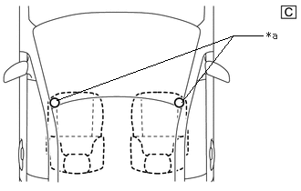
| *a | Electrical Key Transmitter Sub-assembly Inspection Point |
The illustrations shown are examples only.
*3: No. 1 indoor electrical key antenna assembly (front floor)
- HINT:
-
Place the electrical key transmitter sub-assembly on the front seat cushion of the driver seat or front passenger seat.
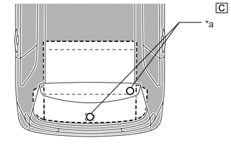
| *a | Electrical Key Transmitter Sub-assembly Inspection Point |
The illustrations shown are examples only.
*4: No. 3 indoor electrical key antenna assembly (inside luggage compartment)
- HINT:
-
Place the electrical key transmitter sub-assembly on the luggage room floor.
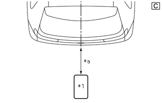
| *1 | Electrical Key Transmitter Sub-assembly |
| *a | 0.7 to 1 m (2.30 to 3.28 ft.) |
The illustrations shown are examples only.
*5: Electrical key antenna (outside luggage compartment)
- HINT:
-
Hold the electrical key transmitter sub-assembly at the same height as the rear bumper upper surface and align it with the center of the rear of the vehicle as shown in the illustration.

| *A | for HV Model |
| *B | for Gasoline Model |
| *1 | Power Switch |
| *2 | Engine Switch |
| *3 | Electrical Key Transmitter Sub-assembly |
The illustrations shown are examples only.
*6: Amplifier (power switch)
- HINT:
-
While facing the logo side of the electrical key transmitter sub-assembly toward the power switch*7 or engine switch*8, hold the transmitter near the power switch*7 or engine switch*8.
*7: for HV Model
*8: for Gasoline Model